Josef Kihlberg a.560BFL Användarmanual
- Kategori
- Elverktyg
- Typ
- Användarmanual

BATTERY-POWERED
TOP STAPLER
BATTERI-DRIVEN
LOCKHÄFTARE
c.561B a.560B
c.561B22 a.560B22
Patent pending
Patentsökt
V 05.19
EN PAGE 2 OPERATING MANUAL
SE SIDA 25 ANVÄNDARHANDBOK

EN 2
Original operating manual according to “Machine Directive” 2006/42/EEC.
Read this manual carefully.
This manual is part of the product and therefore should be kept for later use or a future owner.
Validity
c.561B from Series no 1904xxx
c.561B22 from Series no 1904xxx
a.560B from Series no 1904xxx
a.560B22 from Series no 1904xxx
Manufacturer / Customer service
Josef Kihlberg AB
Industrigatan 37B
544 50 Hjo, SWEDEN
www.kihlberg.com
(or local sevice center)
(for stapling tools with LED indicators only)

EN
TABLE OF CONTENTS
3
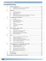
Table of contents
1 General information ................................................................................. 4
1.1 Conventions and symbols used within this manual ...................................... 4
1.2 Disposal and environmental protection ........................................................4
2 Safety ........................................................................................................ 5
2.1 Intended Use ................................................................................................5
2.2 Forseeable misuse .......................................................................................5
2.3 Working safely ..............................................................................................5
2.4 General safety warnings for power tools ......................................................6
2.5 Safety instructions for stapling tools .............................................................8
3 Getting to know your stapler ................................................................ 10
3.1 Overview ....................................................................................................10
3.2 User Interface .............................................................................................11
3.3 Tool status indicator ...................................................................................11
3.4 Battery and charger ....................................................................................11
3.5 Function .....................................................................................................12
3.6 Transporting the stapler .............................................................................13
3.7 Scope of delivery ........................................................................................13
3.8 Optional features ........................................................................................13
4 Preparing for operation ......................................................................... 14
4.1 Charging the battery ...................................................................................14
4.2 Inserting/removing battery from tool ...........................................................14
4.3 Checking charge status ..............................................................................14
4.4 Setting/description of operating modes ......................................................15
4.5 Loading the stapler .....................................................................................15
5 Operation ................................................................................................ 16
5.1 Activating the stapler from sleep mode ......................................................16
5.2 Operating the stapler ..................................................................................16
5.3 Checking staple clinch ...............................................................................17
5.4 Adjusting staple leg length .........................................................................17
5.5 Adjusting penetration depth .......................................................................18
5.6 Adjusting staple clinch ................................................................................18
6 Preventive and corrective maintenance .............................................. 19
6.1 Preventive maintenance schedule .............................................................19
6.2 Cleaning the stapler ...................................................................................19
6.3 Removing jammed staples .........................................................................19
6.4 Removing/installing the magazine .............................................................20
6.5 Cleaning/replacing the driver blade (pos. 3) ..............................................20
6.6 Cleaning/replacing the clinchers (pos. 4) ...................................................21
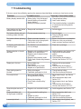
7 Troubleshooting .....................................................................................22
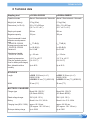
8 Technical data ........................................................................................ 23
EC Declaration of Conformity (copy) ............................................................. 24

EN 4
GENERAL INFORMATION
1 General information
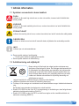
1.1 Conventions and symbols used within this manual
DANGER
Indicates a hazard with a high level of risk, which, if not avoided, will result in death or serious
injury.
WARNING
Indicates a hazard with a moderate level of risk, which, if not avoided, may result in death or
serious injury.
CAUTION
Indicates a hazard with a minor level of risk, which, if not avoided, may result in minor or moder-
ate injury.
ATTENTION
Indicates a situation that can lead to material or environmental damage or poor operating
results.
INFO
Indicates hints and recommendations.
►This symbol identies action steps.
→This symbol indicates results from action steps.
●This symbol identies list items.
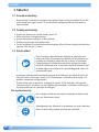
1.2 Disposal and environmental protection
These tools are manufactured without any chemical substances which
could be dangerous to health. Nevertheless, potential health damage
may occur from battery liquid if batteries are treated or disposed of
inadequately. Therefore, it is important to protect health and also
promote the reuse and environmentally-appropriate recycling of waste.
Chargers and batteries should be sorted for environmentally-friendly
recycling and disposed of separately.
The legal prescriptions for disposal of all parts must be observed.
►Chargers and batteries should be sorted for environmentally-friendly recycling.
►Observe warnings and instructions of the battery manufacturer stated in the operating instruc-
tions of the battery.
The following harmonised standards have also been taken into consideration:
●Directive 2011/65/EU of 8 June 2011 on the restriction of the use of certain hazardous substan-
ces in electrical and electronic equipment (RoHS II).
●Directive 2012/19/EU of 4 July 2012 on waste electrical and electronic equipment (WEEE II).

EN
SAFETY
5
2 Safety
2.1 Intended Use
These tools are intended for closing boxes made from cardboard. These tools are intended
for stapling with staples as specied in Section “8”. Only use these tools as described in this
manual.
2.2 Forseeable misuse
●Do not use staples which are not listed in Section “8”.
●Do not place any staples into unsuitable material.
●Never use these tools to attach electrical cables.
●Do not modify tools without prior authorisation.
●If your stapler is equipped with a position guidance laser (option) never direct laser at persons.
Do not look directly into the laser.
2.3 Working safely
This manual must always be available at the place of operation of the
stapling tool. It must be read and observed by all persons working with
or in the vicinity of the stapling tool.
Preventive and corrective maintenance on the tool may only be carried
out by trained personnel. In addition to this manual, the applicable local
rules for accident prevention and safe and professional operation must
be observed.
The operator or his supervisor is responsible for safe stapling and the selection of the correct
staples (as specied in Section “8”) for the package, depending on its dimensions, weight, stabil-
ity and the way it will be transported and stored.
Only staples specied for the tool type (Section “8”) must be used. The tools should be adjusted
appropriately for the staples and the package used. The operator is responsible for the correct
tool settings and adjustments.
Wear protective equipment
When operating the tool, wear hand protection (cut-proof gloves) and
safety shoes.
Safety goggles should always be worn by the operator and others in
the work area when loading, operating or servicing these tools.

EN 6
SAFETY
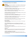
2.4 General safety warnings for power tools
WARNING
Read all safety warnings and all instructions.
Failure to follow the warnings and instructions may result in electric shock, re and/or serious
injury. Save all warnings and instructions for future reference.
The term “power tool” in the warnings refers to your mains-operated (corded) power tool or
battery-operated (cordless) power tool.
2.4.1 Work area safety
a) Keep the work area clean and well lit. Cluttered or dark areas invite accidents.
b) Do not operate power tools in explosive atmospheres, such as in the presence of ammable
liquids, gases or dust. Power tools create sparks which may ignite the dust or fumes.
c) Keep children and bystanders away while operating a power tool. Distractions can cause you to
lose control.
2.4.2 Electrical safety
a) Power tool plugs must match the outlet. Never modify the plug in any way. Do not use any
adapter plugs with earthed (grounded) power tools. Unmodied plugs and matching outlets will
reduce the risk of electric shock.
b) Avoid body contact with earthed or grounded surfaces such as pipes, radiators, ranges and
refrigerators. There is an increased risk of electric shock if your body is earthed or grounded.
c) Do not expose power tools to rain or wet conditions. Water entering a power tool will increase the
risk of electric shock.
d) Do not abuse the cord. Never use the cord for carrying, pulling or unplugging the power tool.
Keep the cord away from heat, oil, sharp edges or moving parts. Damaged or entangled cords
increase the risk of electric shock.
e) When operating a power tool outdoors, use an extension cord suitable for outdoor use. Use of a
cord suitable for outdoor use reduces the risk of electric shock.
f) If operating a power tool in a damp location is unavoidable, use a residual current device (RCD)
protected supply. Use of an RCD reduces the risk of electric shock.
2.4.3 Personal safety
a) Stay alert, watch what you are doing and use common sense when operating a power tool. Do
not use a power tool while you are tired or under the inuence of drugs, alcohol or medication.
A moment of inattention while operating power tools may result in serious personal injury.
b) Use personal protective equipment. Always wear eye protection. Protective equipment such as
dust masks, non-skid safety shoes, hard hat, or hearing protection used for appropriate conditions will
reduce personal injuries.
c) Prevent unintentional starting. Ensure the switch is in the off-position before connecting to the
power source and/or battery pack, picking up or carrying the tool. Carrying power tools with your
nger on the switch or energising power tools that have the switch on invites accidents.
d) Remove any adjusting key or wrench before turning the power tool on. A wrench or a key left
attached to a rotating part of the power tool may result in personal injury.
e) Do not overreach. Keep proper footing and balance at all times. This enables better control of the
power tool in unexpected situations.
f) Dress properly. Do not wear loose clothing or jewellery. Keep your hair, clothing and gloves
away from moving parts. Loose clothes, jewellery or long hair can be caught in moving parts.

EN
SAFETY
7
g) If devices are provided for the connection of dust extraction and collection facilities, ensure
these are connected and properly used. Use of dust collection can reduce dust-related hazards.
2.4.4 Power tool use and care
a) Do not force the power tool. Use the correct power tool for your application. The correct power
tool will do the job better and safer at the rate for which it was designed.
b) Do not use the power tool if the switch does not turn it on and off. Any power tool that cannot be
controlled with the switch is dangerous and must be repaired.
c) Disconnect the plug from the power source and/or the battery pack from the power tool before
making any adjustments, changing accessories, or storing power tools. Such preventive safety
measures reduce the risk of starting the power tool accidentally.
d) Store idle power tools out of the reach of children and do not allow persons unfamiliar with the
power tool or these instructions to operate the power tool. Power tools are dangerous in the hands
of untrained users.
e) Maintain power tools. Check for misalignment or binding of moving parts, breakage of parts and
any other condition that may affect the power tool’s operation. If damaged, have the power tool
repaired before use. Many accidents are caused by poorly maintained power tools.
f) Keep cutting tools sharp and clean. Properly maintained cutting tools with sharp cutting edges are
less likely to bind and are easier to control.
g) Use the power tool, accessories and tool bits etc. in accordance with these instructions, taking
into account the working conditions and the work to be performed. Use of the power tool for
operations different from those intended could result in a hazardous situation.
2.4.5 Battery tool use and care
a) Recharge only with the charger specied by the manufacturer. A charger that is suitable for one
type of battery pack may create a risk of re when used with another battery pack.
b) Use power tools only with specically designated battery packs. Use of any other battery packs
may create a risk of injury and re.
c) When the battery pack is not in use, keep it away from other metal objects, like paper clips,
coins, keys, nails, screws or other small metal objects, that can make a connection from one
terminal to another. Shorting the battery terminals together may cause burns or a re.
d) Under abusive conditions, liquid may be ejected from the battery; avoid contact. If contact
accidentally occurs, ush with water. If liquid contacts eyes, additionally seek medical help. Liquid
ejected from the battery may cause irritation or burns.
2.4.6 Service
a) Have your power tool serviced by a qualied repair person using only identical replacement
parts. This will ensure that the safety of the power tool is maintained.

EN 8
SAFETY
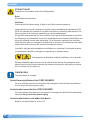
2.5 Safety instructions for stapling tools
WARNING
Read all safety warnings and all instructions in this manual and in the battery charger
operating instructions.
Failure to follow the warnings and instructions may result in electric shock, re and/or serious
injury. The following hazards can result in serious injuries.
Stapling tool safety warnings:
Always assume that the tool contains staples. Careless handling of the stapling tool can
result in unexpected ring of staples and personal injury.
Do not point the tool towards yourself or anyone nearby. Unexpected triggering will dis-
charge the staple causing an injury.
Do not actuate the tool unless the tool is placed rmly against the workpiece. If the tool is
not in contact with the workpiece, the staple may be deected away from your target.
Disconnect the tool from the power source when the staple jams in the tool. While remov-
ing a jammed staple, the stapling tool may be accidentally activated if it is plugged in.
Use caution while removing a jammed staple. The mechanism may be under
compression and the staple may be forcefully discharged while attempting to free a jammed
condition.
Do not use this tool for fastening electrical cables. It is not designed for electric cable
installation and may damage the insulation of electric cables thereby causing electric shock or
re hazards.
Danger of jamming and crushing. Do not place hands or other body parts between or under
the tool and the packaged goods during the stapling process.
Loose and falling packaged goods in the case of faulty stapling.
Check the staple seal. Never transport packaged goods if loads look unbalanced or incorrect.
Risk of explosion in EX (Explosive) zones. The tool must not be used in areas where explo-
sions can occur as a result of the environment or products being used.
Damage due to humidity. Do not clean the tool with water or steam. When using the tool
outdoors, protect it from rain. If the tool or the battery has water damage, it can cause re or
explosion.
Compressed air for cleaning work, risk of injury. When cleaning with compressed air, no air
must penetrate the body via skin lesions. Use only clean and dry compressed air. Use a blow
gun with a multi-hole nozzle. Wear eye protection.

EN
SAFETY
9
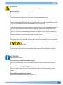
CAUTION
The following dangers can result in minor or moderate injury:
Noise exposure
Wearing hearing protection is recommended.
Vibration exposure
The vibration level of these tools is lower than the permissible exposure limit.
The vibration level specied in this manual has been measured according to a measurement
method standardised in EN 60745 and can be used for the comparison of power tools with each
other. It is also suitable for a preliminary estimation of the vibration load.
The vibration emission value measured may, however, deviate from the specied value depend-
ing on the actual application and the manner of operation. Under certain circumstances, the
vibration load may be increased temporarily or may be signicantly smaller over the entire work
period. For a more accurate assessment of the actual vibration load, the times should also be
considered when the device is switched off, or is running but not actually being used. This could
reduce the vibration load signicantly over the entire work period.
Therefore, dene additional safety measures against the effect of vibrations for the protection of
the operator, such as, for example: maintenance of the tool and organisation of work processes.
Warning sign on protection plate at the bottom of the stapler and on rear
housing.
Since the box detection sensors do not distinguish between cardboard and e.g. by the ngers
of the operator, there is a risk that the operator may be injured when operating the trigger by
driving staples (extending driver blade and clinchers).
ATTENTION
Avoid damage to the tool:
Use only original JOSEF KIHLBERG staples.
Using non-original staples may impair operational safety and will void the warranty and any
liability.
Use only original JOSEF KIHLBERG spare parts.
Using non-original spare parts may impair operational safety will void the warranty and any
liability.
Use only Bosch batteries and chargers.
Batteries and chargers are described in Section “3.7”.

EN 10
GETTING TO KNOW YOUR STAPLER
3 Getting to know your stapler
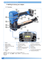
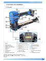
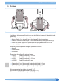
3.1 Overview
1 Battery
2 Battery release
3 Magazine pusher
4 Magazine with staple type
indication
5 Staples
6 Safety latch
7 Trigger
8 Magazine quick snap system
9 Tool status indicator
10 Screw for staple length
adjustment
11 Penetration depth setting knob
12 Staple clinch adjusting nut
13 Mode button
14 Suspension hanging port
(for stationary workplaces)
15 Battery charge status indicator
16 Clinchers
17 Box detection
18 Locking screw
(for staple length adjustment)
19 Company label (sticker)
Serial number syntax is as follows (JJMMYYYY)
JJ → Year; MM → Month; YYYY → consecutive number
13 3
7
1
8
9
11
10
17
16 16
4
5
15
2
18
14
6
19
17
11
12

EN
GETTING TO KNOW YOUR STAPLER
11
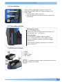
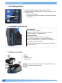
3.2 User Interface
1 Display “Battery charge status” (see also Section “4.3”)
2 Mode indicators: MAN, SEMI, AUTO (see also Section “4.4”)
3 Button “Mode”
→One click: select mode of operation
→Hold button (approx. one second): activate or deactivate
optional laser
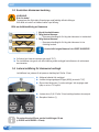
3.3 Tool status indicator
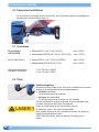
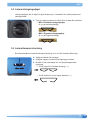
3.4 Battery and charger
1 Battery
2 Charger
3 Battery release
4 LED indicator
For detailed information, refer to the operating instructions
of battery and charger.
1
2
3
2
1
3
Whilst getting started:
blue LED pulsating twice:
indicates that battery has been inserted and trigger has
been actuated once → tool turns on
During operation:
blue LED slowly pulsating “ready for operation”
green LED permanently on “tool in stapling position”:
indicates activated box detection and nger on trigger
(trigger sensor)
red LED slowly pulsating / permanently on “tool error”:
(see also Section “7”)
1
4
2
3

EN 12
GETTING TO KNOW YOUR STAPLER
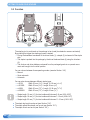
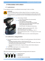
3.5 Function
The stapling tool is positioned on the package to be closed (box detection sensors activated).
By actuating the trigger the stapling process is started:
→During the downward movement of the driver blade (1), a staple (2) is sheared off the staple
strip.
→The staple is pushed into the package by the driver blade and bent (4) using the clinchers
(3).
→The clincher and driver blade are released from the packaged goods in an upward move-
ment and brought into the initial position.
You can choose between three operating modes: (see also Section “4.4”)
→Manual
→Semi-automatic
→Automatic
You can also choose between different staple types:
→c.561B: Width 32 mm (11/4″) / Length 15–18 mm (5/8–3/4″)
→c.561B22: Width 32 mm (11/4″) / Length 22 mm (7/8″)
→a.560B: Width 35 mm (13/8″) / Length 15–18 mm (5/8–3/4″)
→a.560B22: Width 35 mm (13/8″) / Length 22 mm (7/8″)
→Staple length 15 mm (5/8″) for total cardboard thickness 5–9 mm (0.20–0.35″)
→Staple length 18 mm (3/4″) for total cardboard thickness 7–12 mm (0.28–0.47″)
→Staple length 22 mm (7/8″) for total cardboard thickness 11–16 mm (0.43–0.63″)
●The staple leg length can be set (see Section “5.4”).
●The staple penetration depth can be set (see Section “5.5”).
●The staple clinch can be set (see Section “5.6”).
4
2
3
1

EN
GETTING TO KNOW YOUR STAPLER
13
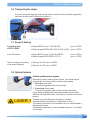
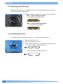
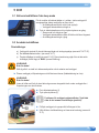
3.6 Transporting the stapler
To prevent accidental triggering while carrying the tool, make sure that the handle is gripped by
hand and the index nger is behind the shoulder (1).
3.7 Scope of delivery
For stapling tools
c.561B / a.560B: ●Battery BOSCH Li-Ion 12 V/4.0 Ah (EU) part no 137035
●Battery charger BOSCH GAL 1230 CV (230 V) (EU) part no 137033
or for USA version: ●Battery BOSCH Li-Ion 12 V/4.0 Ah, BAT420 part no 137034
●Battery charger BOSCH BC330 (115 V) part no 137032
Tool kit consisting of (including
in the scope of delivery) ●Allen key Torx T10, part no 942070
●Allen key Torx T20, part no 942071
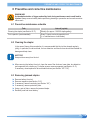
3.8 Optional features
Position guidance laser system
Depending on which model you have chosen, your stapler may be
equipped with one of two position guidance laser systems:
●Line-Laser (front laser)
For positioning guidance with one front laser.
●Cross-Laser (three lasers)
For positioning guidance with one front and two side lasers.
If your stapler is equipped with this position guidance laser feature,
additional risks may be involved, if the laser is, for instance, directed at
persons:
The laser is only activated when the trigger is actuated.
A disruptive effect is possible with a laser device of class 1.
This means that persons in the immediate vicinity can feel disturbed or
distracted by the laser.
(Predictable misapplication: Laser is directed at persons. Look directly
into the laser)
1
LASER 1

EN 14
PREPARING FOR OPERATION
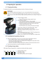
4 Preparing for operation
4.1 Charging the battery
For detailed information, see enclosed operating instructions of battery and charger.
WARNING
Only use Bosch batteries and chargers for your country as described in this manual (see
Section “3.7”). Use of other batteries/chargers can result in injury or re. To avoid the risk of
personal injury or re, read the battery charger operating instructions prior using the charger and
battery.
►Connect charger to mains.
→Green LED illuminates (charger ready for use).
►Insert battery in charger.
→Green LED ashes: Battery is being charged.
→Green LED illuminates continuously: Battery is fully charged.
→Red LED illuminates continuously: Battery temperature
outside charge-temperature range.
→Red LED ashes: see operating instructions for charger.
●Charging time: Charging of empty battery (80% / 100%):
approx. 60 / 80 min. (US: approx. 120 / 160 min.)
●Ideal battery temperature during charging process: 15–40 °C
(59–104 °F)
●Avoid battery temperatures below 0 °C (32 °F) and higher than
+45 °C (113 °F) during the charging process.
●Battery can be charged at any time, regardless of charge status.
4.2 Inserting/removing battery from tool
►Insert the charged battery into the tool. The unlock buttons must engage in the tool.
→The tool status indicator, indicates: Bright blue pulsating LED (2x).
→If the tool is not used for approx. two minutes the tool changes into sleep mode. Cancel
sleep mode by actuating trigger once.
→If the tool is not used for a long period (days) the battery must be removed from the tool.
►Press the unlock buttons and remove the battery at the same time.
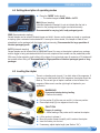
4.3 Checking charge status
LED display "Battery charge status" on digital user interface with battery inserted:
1 maximum battery charge
2 high battery charge
3 good battery charge
4 empty battery (battery must be charged)
12 3 4

EN
PREPARING FOR OPERATION
15
hold
hold
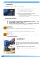
4.4 Setting/description of operating modes
►Press the “MODE” button shortly.
→The mode changes to MAN, SEMI or AUTO.
MAN (Manual stapling)
Individual staples are inserted. A cycle is initiated after the tool is
placed on the package and the trigger is actuated manually.
Recommended for varying (soft, hard) packaged goods.
SEMI (Semi-automatic stapling)
Several staples can be inserted. Actuate trigger and hold it. As soon as the stapler is placed on a package,
a stapling cycle is activated via box detection. A new cycle is then started, if the stapler is lifted off and
placed back on the package (with the trigger held continuously). Recommended for large quantities of
identical packaged goods.
AUTO (Automatic stapling)
Several staples can be inserted over a predened interval. As soon as the stapler is placed on a package
and the trigger is being actuated and held in this mode, staples will be inserted over the predened period.
With every further actuation (and holding) of the trigger, this cycle starts anew. A maximum of 20 staples will
be inserted without lifting off. Recommended for large quantities of identical packaged goods or long
packages.
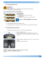
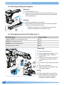
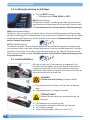
4.5 Loading the stapler
There is a reloading mark (arrow) (1) on both sides of the magazine. If
there are just a few staples left in the magazine, the staples should be
lled up. The correct type of staple is marked on the left side of the
magazine. Make sure to use the right length of staples for your
application.
WARNING
Unexpected startup during loading.
• Remove the battery!
►Pull the pusher (2) all the way out and x it in the rear position.
►Place staple strips (3) into magazine from the top.
CAUTION
Danger of crushing.
• Active feeding of the pusher until it reaches the staples.
►Lift the pusher to release it.
►Move the pusher forward carefully until it reaches the staples.
►Insert the battery into the tool.
►If necessary, adjust staple length (see Section “5.4”)
1
2
3
3

EN 16
OPERATION
5 Operation
5.1 Activating the stapler from sleep mode
To avoid unnecessary battery discharge, the tool switches to ener-
gy-saving mode (sleep mode) after a short time.
→The user interface goes dark (not illuminated).
→The tool status indicator is switched off.
►Release the safety latch and actuate the trigger once.
→The sleep mode is switched off again.
→The tool status indicator changes to blue and pulsates slowly.
→The user interface switches on.
5.2 Operating the stapler
Preconditions
a) The tool is adjusted to correct staple lengths and penetration depth (see Section “5.4”/“5.5”).
b) The charged battery is inserted (see Section “4.2”).
c) The desired operating mode is set (see Section “4.4”). In this description it is assumed that
the selected operating mode (default mode) is “MAN” (manual stapling).
WARNING
Danger of injury!
Always place yourself in a rmly balanced position when using or handling the tool.
►Place tool on package and hold the tool against package (box detection covered).
WARNING
Danger of injury!
Before stapling, ensure that your hand or any other part of your body is not underneath the tool
or in the package to be closed.
►Pull the safety latch (1).
►Actuate the trigger (2).
The position of the tool status indicator (3) on both
sides of the tool is equal to the stapling line (position).
►Move the tool and repeat until the stapling is nished.
►Carry out a visual inspection of the staple clinch (see Section
“5.3”).
3
1
2

EN
OPERATION
17
5.3 Checking staple clinch
WARNING
Danger of injury!
Never transport or move packaged goods with improperly performed stapling.
Perform staple check after each stapling.
Performing a staple check by visual inspection
1 Good staple clinch
2 Poor staple clinch
→Leg length of staple too long or overbent
3 Poor staple clinch
→Leg length of staple too short or not bent enough
Always use JOSEF KIHLBERG original staples!
►If necessary adjust staple clinch (see Section “5.6”).
►If good stapling is not achieved, the tool must be checked by an authorized service center.
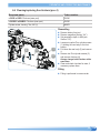
5.4 Adjusting staple leg length
The stapler can be adjusted to a 15 (5/8″) or 18 mm (3/4″) staple leg length.
►Remove battery from tool.
►Adjust penetration depth to deep (MAX) (see Section “5.5”).
►With a Torx T10 key, unscrew locking screw (1) below the tool by
two turns.
►With a screwdriver, adjust screw (2) to 15 (5/8″) or 18 mm (3/4″) leg
length.
►Retighten the locking screw (1).
For 22 mm (7/8″) staple leg length, use 18 mm (3/4″) setting
(c.561B22 and a.560B22 = 22 mm (7/8″).
1
2
3
1
2
15 mm18 mm

EN 18
OPERATION
5.5 Adjusting penetration depth
The depth of the stapling, i. e. the extent to which the driver plate penetrates the material, is
easy to adjust using the setting knob.
►Depress the setting knob and turn it to any of its ve positions.
→MIN = Lowest stapling penetration
(i. e. smallest resulting leg length)
→MAX = Deepest stapling penetration
(i. e. longest resulting leg length)
5.6 Adjusting staple clinch
It is recommended to adjust the staple clinch, i. e. how tightly the staples close.
►Remove battery from tool.
►Remove housing plug over slot.
►With a small screwdriver turn the adjusting nut behind the slot:
→Turn to the right to close the clinch (→).
→Turn to the left to open up the clinch (←).

EN
PREVENTIVE AND CORRECTIVE MAINTENANCE
19
6 Preventive and corrective maintenance
WARNING
Unintended actuation of trigger and safety latch during maintenance work could lead to
injuries. Always remove battery before performing cleaning or preventive and corrective mainte-
nance work.
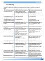
6.1 Preventive maintenance schedule
Task Interval (cycles)
Cleaning the stapler (see Section “6.2”) Weekly (for approx. 100-300 staplings/day)
Tool inspection (recommended) Every 2 years, service by specialist unit
(i. e. manufacturer or local dealer)
6.2 Cleaning the stapler
In the case of heavy dirt accumulation it is recommended that the tool be cleaned regularly
(daily). In particular, the driver blade, the box detection and the clinchers should be checked for
damage and kept clean.
NOTICE
Keep moisture away from the tool.
►After removing the battery from tool, clean the area of the clinchers, base plate, box detection
and magazine with a clean rag. For better access, remove magazine (see Section “6.4”).
If necessary, clean/replace the driver blade/clinchers (see Section “6.5”/“6.6”).
6.3 Removing jammed staples
►Remove battery from tool.
►Remove magazine (see Section “6.4”).
►If necessary, remove rear body (see Section “6.5”).
►If necessary, remove protection plate.
►Using a pair of pliers, remove the jammed staple.
►Reinstall parts and insert battery.

EN 20
PREVENTIVE AND CORRECTIVE MAINTENANCE
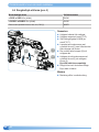
6.4 Removing/installing the magazine
Removing
►Remove battery from tool.
►Press the quick release buttons on left and right side (1) on the
stapler and pull the magazine (2) backwards (a) and afterwards
pull it downwards (b).
Installing
►Installing is performed in reverse order.
►When installing the magazine make sure that the quick release
buttons (1) are ush with the housing.
→Only then the latching of the magazine is ensured and no
malfunction (stable jam) can occur as a result.
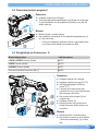
6.5 Cleaning/replacing the driver blade (pos. 3)
Required parts Order number
c.561B /c.561B22: Driver blade (wear part) 164175
a.560B: Driver blade (wear part) 164176
a.560B22: Driver blade (wear part) 164177
Cylinder screw Torx, M4 (1) 946876
Dismantling
►Remove battery from tool.
►Remove magazine (see Section “6.4”).
►Set penetration depth to MIN (see
Section “5.5”).
►Loosen six captive cylinder screws Torx
(1) holding the rear body to the front
section.
►Pull down the rear body (2) and remove
it.
►Remove driver blade (3).
►Clean and check driver blade for wear,
if necessary replace it.
Fitting
►Fitting is performed in reverse order.
►When installing the driver blade, make
sure that the signage “visible while
assembling” (4) points outwards.
2
1
a
b
4
1
2
3
Sidan laddas...
Sidan laddas...
Sidan laddas...
Sidan laddas...
Sidan laddas...
Sidan laddas...
Sidan laddas...
Sidan laddas...
Sidan laddas...
Sidan laddas...
Sidan laddas...
Sidan laddas...
Sidan laddas...
Sidan laddas...
Sidan laddas...
Sidan laddas...
Sidan laddas...
Sidan laddas...
Sidan laddas...
Sidan laddas...
Sidan laddas...
Sidan laddas...
Sidan laddas...
Sidan laddas...
Sidan laddas...
Sidan laddas...
Sidan laddas...
Sidan laddas...
-
 1
1
-
 2
2
-
 3
3
-
 4
4
-
 5
5
-
 6
6
-
 7
7
-
 8
8
-
 9
9
-
 10
10
-
 11
11
-
 12
12
-
 13
13
-
 14
14
-
 15
15
-
 16
16
-
 17
17
-
 18
18
-
 19
19
-
 20
20
-
 21
21
-
 22
22
-
 23
23
-
 24
24
-
 25
25
-
 26
26
-
 27
27
-
 28
28
-
 29
29
-
 30
30
-
 31
31
-
 32
32
-
 33
33
-
 34
34
-
 35
35
-
 36
36
-
 37
37
-
 38
38
-
 39
39
-
 40
40
-
 41
41
-
 42
42
-
 43
43
-
 44
44
-
 45
45
-
 46
46
-
 47
47
-
 48
48


Josef Kihlberg a.560BFL Användarmanual
- Kategori
- Elverktyg
- Typ
- Användarmanual
på andra språk
- English: Josef Kihlberg a.560BFL User manual
Relaterade papper
-
Josef Kihlberg a.560PN Användarmanual
-
-
-
-
-
-
-