Makita UC100D Användarmanual
- Kategori
- Kraft motorsågar
- Typ
- Användarmanual

UC100D
EN Cordless Pruning Saw INSTRUCTION MANUAL 8
SV Batteridriven grensåg BRUKSANVISNING 18
NO Batteridrevet beskjæringssag BRUKSANVISNING 28
FI Akkukäyttöinen karsintasaha KÄYTTÖOHJE 38
DA Akku beskæringssav BRUGSANVISNING 48
LV Akumulatora atzarošanas
ķēdes zāģis LIETOŠANAS INSTRUKCIJA 59
LT Akumuliatorinis grandininis
genėjimo pjūklas NAUDOJIMO INSTRUKCIJA 70
ET Akukettsaag KASUTUSJUHEND 81
RU Аккумуляторная цепная
пила РУКОВОДСТВО ПО
ЭКСПЛУАТАЦИИ 91

2
Fig.1
1
2
3
4
5
8
10
9
6
12 7
11
Fig.2
3
1
2
Fig.3
1
2
Fig.4

3
1
2
Fig.5
1
Fig.6
2
1
Fig.7
1
Fig.8
1
2
Fig.9
1
3
2
Fig.10

4
1
2
Fig.11
1
Fig.12
1
Fig.13
1
2
3
Fig.14
3
2
1
Fig.15
1
2
Fig.16
1
Fig.17
2
1
Fig.18

5
1
2
Fig.19
1
2
Fig.20
1
23
Fig.21
21
Fig.22
Fig.23
Fig.24

6
1
2
Fig.25
22
11
31
Fig.26
30
30
55 55
Fig.27
1
2
Fig.28
30
1/5
1
Fig.29
Fig.30
Fig.31
Fig.32

7
2
1
Fig.33
1
2
Fig.34
2
1
Fig.35

8ENGLISH
ENGLISH (Original instructions)
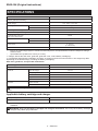
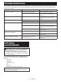
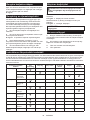
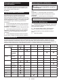
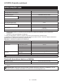
SPECIFICATIONS
Model: UC100D
Overall length
(without guide bar and battery)
350 mm
Rated voltage D.C. 10.8 V - 12 V max
Net weight *1 1.0 kg
*2 1.5 - 1.6 kg
Standard guide bar length 100 mm
Recommended guide bar length 100 mm
Applicable saw chain type
(refer to the table below)
80TXL
Sprocket Number of teeth 7
Pitch 0.325″
Chain speed 0 - 8.0 m/s
(0 - 480 m/min)
Chain oil tank volume 55 cm3
• Duetoourcontinuingprogramofresearchanddevelopment,thespecicationshereinaresubjecttochange
without notice.
• Specicationsmaydierfromcountrytocountry.
*1: Weight, without the saw chain, guide bar, guide bar cover, oil and battery cartridge(s).
*2:Thelightestandheaviestcombinationofweight,accordingtoEPTA-Procedure01/2014.Theweightmaydier
depending on the attachment(s), including the battery cartridge(s).
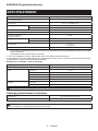
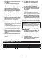
Saw chain, guide bar, and sprocket combination
Saw chain type 80TXL
Number of drive links 26
Guide bar Guide bar length 100 mm
Cutting length 111 mm
Pitch 0.325″
Gauge 1.1 mm
Type Hard nose bar
Sprocket Number of teeth 7
Pitch 0.325″
WARNING:Useappropriatecombinationoftheguidebarandsawchain.Otherwisepersonalinjurymay
result.
Applicable battery cartridge and charger
Battery cartridge BL1016 / BL1021B / BL1041B
Charger DC10SA / DC10SB / DC10WC / DC10WD / DC18RE
• Some of the battery cartridges and chargers listed above may not be available depending on your region of
residence.
WARNING: Only use the battery cartridges and chargers listed above. Use of any other battery cartridges
andchargersmaycauseinjuryand/orre.

9ENGLISH
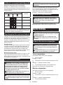
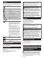
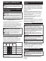
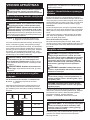
Symbols
The followings show the symbols which may be used
for the equipment. Be sure that you understand their
meaning before use.
Read instruction manual.
Wear safety glasses and ear protection.
Always use two hands when operating
the tool.
Beware of kickback and avoid contact with
bar tip.
Do not expose to moisture.
Maximum permissible cut length
Direction of chain travel
Ni-MH
Li-ion
Only for EU countries
Due to the presence of hazardous com-
ponents in the equipment, waste electrical
and electronic equipment, accumulators
and batteries may have a negative impact
on the environment and human health.
Do not dispose of electrical and electronic
appliances or batteries with household waste!
In accordance with the European Directive
on waste electrical and electronic equipment
and on accumulators and batteries and
waste accumulators and batteries, as well as
their adaptation to national law, waste elec-
trical equipment, batteries and accumulators
should be stored separately and delivered
to a separate collection point for municipal
waste, operating in accordance with the
regulations on environmental protection.
This is indicated by the symbol of the
crossed-out wheeled bin placed on the
equipment.
Guaranteed sound power level according
to EU Outdoor Noise Directive.
Sound power level according to Australia
NSW Noise Control Regulation.
Intended use
This tool is intended for cutting branches of trees or
bushes by means of a saw-chain.
Noise
The typical A-weighted noise level determined accord-
ing to EN62841-4-1:
Sound pressure level (LpA) : 76 dB (A)
Sound power level (LWA) : 87 dB (A)
Uncertainty (K) : 3 dB (A)
NOTE:
The declared noise emission value(s) has been
measured in accordance with a standard test method
and may be used for comparing one tool with another.
NOTE:
The declared noise emission value(s) may
also be used in a preliminary assessment of exposure.
WARNING: Wear ear protection.
WARNING:
The noise emission during actual
use of the power tool can dier from the declared
value(s) depending on the ways in which the tool is
used especially what kind of workpiece is processed.
WARNING: Be sure to identify safety mea-
sures to protect the operator that are based on an
estimation of exposure in the actual conditions of
use (taking account of all parts of the operating
cycle such as the times when the tool is switched
o and when it is running idle in addition to the
trigger time).
Vibration
The vibration total value (tri-axial vector sum) deter-
mined according to EN62841-4-1:
Work mode: cutting wood
Vibration emission (ah,W) : 4.8 m/s2
Uncertainty (K) : 1.5 m/s2
NOTE: The declared vibration total value(s) has been
measured in accordance with a standard test method
and may be used for comparing one tool with another.
NOTE: The declared vibration total value(s) may also
be used in a preliminary assessment of exposure.
WARNING: The vibration emission during
actual use of the power tool can dier from the
declared value(s) depending on the ways in which
the tool is used especially what kind of workpiece
is processed.
WARNING: Be sure to identify safety mea-
sures to protect the operator that are based on an
estimation of exposure in the actual conditions of
use (taking account of all parts of the operating
cycle such as the times when the tool is switched
o and when it is running idle in addition to the
trigger time).
Declarations of Conformity
For European countries only
The Declarations of conformity are included in Annex A
to this instruction manual.
SAFETY WARNINGS
General power tool safety warnings
WARNING Read all safety warnings, instructions,
illustrations and specications provided with this
power tool. Failure to follow all instructions listed below
mayresultinelectricshock,reand/orseriousinjury.
Save all warnings and instruc-
tions for future reference.
The term "power tool" in the warnings refers to your
mains-operated (corded) power tool or battery-operated
(cordless) power tool.

10 ENGLISH
General pruner saw safety warnings
1. Keep all parts of the body away from the
saw chain when the pruner saw is operating.
Before you start the pruner saw, make sure
the saw chain is not contacting anything. A
moment of inattention while operating pruner saws
may cause entanglement of your clothing or body
with the saw chain.
2. Always hold the pruner saw with one hand
on the rear handle and the other hand on the
auxiliary handle.
3. Hold the pruner saw by insulated gripping
surfaces only, because the saw chain may con-
tact hidden wiring. Saw chains contacting a "live"
wire may make exposed metal parts of the pruner
saw "live" and could give the operator an electric
shock.
4. Wear eye protection. Further protective equip-
ment for hearing, head, hands, legs and feet is
recommended. Adequate protective equipment
willreducepersonalinjuryfromyingdebrisor
accidental contact with the saw chain.
5. Do not operate a pruner saw in a tree, on a lad-
der, from a rooftop, or any unstable support.
Operation of a pruner saw in this manner could
resultinseriouspersonalinjury.
6. Always keep proper footing and operate the
pruner saw only when standing on xed,
secure and level surface. Slippery or unstable
surfaces may cause a loss of balance or control of
the pruner saw.
7. When cutting a branch that is under tension,
be alert for spring back. When the tension in the
woodbresisreleased,thespringloadedbranch
may strike the operator and/or throw the pruner
saw out of control.
8. Use extreme caution when cutting brush and
saplings. The slender material may catch the saw
chainandbewhippedtowardyouorpullyouo
balance.
9. Carry the pruner saw with the pruner saw
switched o and away from your body. When
transporting or storing the pruner saw, always
t the guide bar cover. Proper handling of the
pruner saw will reduce the likelihood of accidental
contact with the moving saw chain.
10. Follow instructions for lubricating, chain
tensioning and changing the bar and chain.
Improperly tensioned or lubricated chain may
either break or increase the chance for kickback.
11. Cut wood only. Do not use pruner saw for pur-
poses not intended. For example: do not use
pruner saw for cutting metal, plastic, masonry
or non-wood building materials. Use of the
prunersawforoperationsdierentthanintended
could result in a hazardous situation.
12. This pruner saw is not intended for tree felling.
Useoftheprunersawforoperationsdierentthan
intendedcouldresultinseriousinjurytotheopera-
tor or bystanders.
13. Follow all instructions when clearing jammed
material, storing or servicing the pruner saw.
Make sure the switch is o and the battery
pack is removed.
14. Causes and operator prevention of kickback:
Kickback may occur when the nose or tip of the
guidebartouchesanobject,orwhenthewood
closes in and pinches the saw chain in the cut.
Tip contact in some cases may cause a sudden
reverse reaction, kicking the guide bar up and
back towards the operator.
Pinching the saw chain along the top of the guide
bar may push the guide bar rapidly back towards
the operator.
Either of these reactions may cause you to lose
control of the saw which could result in serious
personalinjury.Donotrelyexclusivelyuponthe
safety devices built into your saw. As a pruner saw
user, you should take several steps to keep your
cuttingjobsfreefromaccidentorinjury.
Kickback is the result of pruner saw misuse and/or
incorrect operating procedures or conditions and
can be avoided by taking proper precautions as
given below:
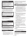
• Maintain a rm grip, with thumbs and n-
gers encircling the pruner saw handles,
with both hands on the saw and position
your body and arm to allow you to resist
kickback forces. Kickback forces can be
controlled by the operator, if proper precau-
tions are taken. Do not let go of the pruner
saw.
►Fig.1
• Do not overreach and do not cut above
shoulder height. This helps prevent unin-
tended tip contact and enables better control
of the pruner saw in unexpected situations.
• Only use replacement guide bars and saw
chains specied by the manufacturer.
Incorrect replacement guide bars and saw
chains may cause chain breakage and/or
kickback.
• Follow the manufacturer’s sharpening
and maintenance instructions for the saw
chain. Decreasing the depth gauge height
can lead to increased kickback.
15. Follow all instructions when clearing jammed
material, storing or servicing the pruner saw.
Make sure the switch is o and the battery
pack is removed.
Additional Safety Instructions
Personal protective equipment
1. Clothing must be close-tting, but must not
obstruct mobility.
2. Wear the following protective clothing during
work:
• A tested safety helmet, if a hazard is pre-
sented by falling branches or similar;
• A face mask or goggles;
• Suitableearprotection(earmus,customor
mouldable ear plugs). Octave brand analysis
upon request.
• Firm leather safety gloves;
• Long trousers manufactured from strong
fabric;
• Protective dungarees of cut-resistant fabric;

11 ENGLISH
• Safety shoes or boots with non-slip soles,
steel toes, and cut-resistant fabric lining;
• A breathing mask, when carrying out work
which produces dust (e.g. sawing dry wood).
Operation
1. Before starting work, check that the tool is in
proper working order and that its condition
complies with the safety regulations. Check in
particular that:
• The run-down brake is working properly;
• Thebarandthesprocketcoveraretted
correctly;
• The chain has been sharpened and ten-
sioned in accordance with the regulations.
2. Do not start the tool with the chain cover being
installed on it. Starting the tool with the chain
cover being installed on it may cause the chain
cover to thrown out forward resulting in personal
injuryanddamagetoobjectsaroundtheoperator.
3. Do not stand directly under the branch that
is being cut. Pay attention to the falling
branches.
4. Do not operate the tool in bad weather or if
there is a risk of lightning.
5. When you use the tool on muddy ground, wet
slope, or slippery place, pay attention to your
footing.
Electrical and battery safety
1. Avoid dangerous environment. Don't use the
tool in dump or wet locations or expose it to
rain. Water entering the tool will increase the risk
of electric shock.
2. Do not dispose of the battery(ies) in a re.
The cell may explode. Check with local codes for
possible special disposal instructions.
3. Do not open or mutilate the battery(ies).
Released electrolyte is corrosive and may cause
damage to the eyes or skin. It may be toxic if
swallowed.
4. Do not charge battery in rain, or in wet
locations.
5. Do not charge the battery outdoors.
6. Do not handle charger, including charger plug,
and charger terminals with wet hands.
7. Do not replace the battery with wet hands.
8. Do not leave the battery in the rain, nor charge,
use, or store the battery in a damp or wet
place.
9. Do not wet the terminal of battery with liquid
such as water, or submerge the battery. If the
terminal gets wet or liquid enters inside of battery,
the battery may be short circuited and there is a
riskofoverheat,re,orexplosion.
10. After removing the battery from the machine or
charger, be sure to attach the battery cover to
the battery and store it in a dry place.
11. If the battery cartridge gets wet, drain the
water inside and then wipe it with a dry cloth.
Dry the battery cartridge completely in a dry
place before use.
SAVE THESE INSTRUCTIONS.
WARNING: DO NOT let comfort or familiarity
with product (gained from repeated use) replace
strict adherence to safety rules for the subject
product. MISUSE or failure to follow the safety
rules stated in this instruction manual may cause
serious personal injury.
Important safety instructions for
battery cartridge
1. Before using battery cartridge, read all instruc-
tions and cautionary markings on (1) battery
charger, (2) battery, and (3) product using
battery.
2. Do not disassemble or tamper with the battery
cartridge.Itmayresultinare,excessiveheat,
or explosion.
3. If operating time has become excessively
shorter, stop operating immediately. It may
result in a risk of overheating, possible burns
and even an explosion.
4. If electrolyte gets into your eyes, rinse them
out with clear water and seek medical atten-
tion right away. It may result in loss of your
eyesight.
5. Do not short the battery cartridge:
(1) Do not touch the terminals with any con-
ductive material.
(2) Avoid storing battery cartridge in a con-
tainer with other metal objects such as
nails, coins, etc.
(3) Do not expose battery cartridge to water
or rain.
A battery short can cause a large current
ow, overheating, possible burns and even a
breakdown.
6. Do not store and use the tool and battery car-
tridge in locations where the temperature may
reach or exceed 50 °C (122 °F).
7. Do not incinerate the battery cartridge even if
it is severely damaged or is completely worn
out. The battery cartridge can explode in a re.
8. Do not nail, cut, crush, throw, drop the battery
cartridge, or hit against a hard object to the
battery cartridge. Such conduct may result in a
re,excessiveheat,orexplosion.
9. Do not use a damaged battery.
10. The contained lithium-ion batteries are subject
to the Dangerous Goods Legislation require-
ments.
For commercial transports e.g. by third parties,
forwarding agents, special requirement on pack-
aging and labeling must be observed.
For preparation of the item being shipped, consult-
ing an expert for hazardous material is required.
Please also observe possibly more detailed
national regulations.
Tapeormaskoopencontactsandpackupthe
battery in such a manner that it cannot move
around in the packaging.
11. When disposing the battery cartridge, remove
it from the tool and dispose of it in a safe
place. Follow your local regulations relating to
disposal of battery.

12 ENGLISH
12. Use the batteries only with the products
specied by Makita. Installing the batteries to
non-compliantproductsmayresultinare,exces-
sive heat, explosion, or leak of electrolyte.
13. If the tool is not used for a long period of time,
the battery must be removed from the tool.
14. During and after use, the battery cartridge may
take on heat which can cause burns or low
temperature burns. Pay attention to the han-
dling of hot battery cartridges.
15. Do not touch the terminal of the tool imme-
diately after use as it may get hot enough to
cause burns.
16. Do not allow chips, dust, or soil stuck into the
terminals, holes, and grooves of the battery
cartridge.Itmaycauseheating,catchingre,
burst and malfunction of the tool or battery car-
tridge,resultinginburnsorpersonalinjury.
17. Unless the tool supports the use near
high-voltage electrical power lines, do not use
the battery cartridge near high-voltage electri-
cal power lines. It may result in a malfunction or
breakdown of the tool or battery cartridge.
18. Keep the battery away from children.
SAVE THESE INSTRUCTIONS.
CAUTION: Only use genuine Makita batteries.
Use of non-genuine Makita batteries, or batteries that
have been altered, may result in the battery bursting
causingres,personalinjuryanddamage.Itwill
also void the Makita warranty for the Makita tool and
charger.
Tips for maintaining maximum
battery life
1. Charge the battery cartridge before completely
discharged. Always stop tool operation and
charge the battery cartridge when you notice
less tool power.
2. Never recharge a fully charged battery car-
tridge. Overcharging shortens the battery
service life.
3. Charge the battery cartridge with room tem-
perature at 10 °C - 40 °C (50 °F - 104 °F). Let
a hot battery cartridge cool down before
charging it.
4. When not using the battery cartridge, remove
it from the tool or the charger.
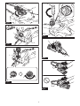
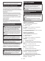
PARTS DESCRIPTION
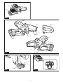
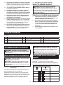
►Fig.2
1Auxiliary handle 2Safety cover 3Saw chain
4Guide bar 5Oil tank cap 6Guide bar cover
7Sprocket cover 8Lock-olever 9Rear handle
10 Switch trigger 11 Lever 12 Battery cartridge
FUNCTIONAL
DESCRIPTION
CAUTION: Always be sure that the tool is
switched o and the battery cartridge is removed
before adjusting or checking function on the tool.
Installing or removing battery
cartridge
CAUTION: Always switch o the tool before
installing or removing of the battery cartridge.
CAUTION: Hold the tool and the battery car-
tridge rmly when installing or removing battery
cartridge. Failure to hold the tool and the battery
cartridgermlymaycausethemtoslipoyourhands
and result in damage to the tool and battery cartridge
andapersonalinjury.
►Fig.3: 1. Red indicator 2. Button 3. Battery cartridge
To remove the battery cartridge, slide it from the tool
while sliding the button on the front of the cartridge.
To install the battery cartridge, align the tongue on the
battery cartridge with the groove in the housing and slip
it into place. Insert it all the way until it locks in place
with a little click. If you can see the red indicator as
showninthegure,itisnotlockedcompletely.
CAUTION: Always install the battery cartridge
fully until the red indicator cannot be seen. If not,
itmayaccidentallyfalloutofthetool,causinginjuryto
you or someone around you.
CAUTION: Do not install the battery cartridge
forcibly. If the cartridge does not slide in easily, it is
not being inserted correctly.

13 ENGLISH
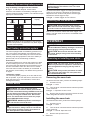
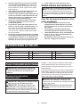
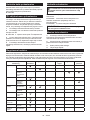
Indicating the remaining battery capacity
Only for battery cartridges with the indicator
►Fig.4: 1. Indicator lamps 2. Check button
Press the check button on the battery cartridge to indi-
cate the remaining battery capacity. The indicator lamps
light up for a few seconds.
Indicator lamps Remaining
capacity
Lighted O
75% to 100%
50% to 75%
25% to 50%
0% to 25%
NOTE: Depending on the conditions of use and the
ambienttemperature,theindicationmaydierslightly
from the actual capacity.
Tool / battery protection system
The tool is equipped with a tool/battery protection sys-
tem.Thissystemautomaticallycutsopowertothe
motor to extend tool and battery life. The tool will auto-
matically stop during operation if the tool or battery is
placed under one of the following conditions:
Overloaded:
The tool is operated in a manner that causes it to draw
an abnormally high current. In this situation, turn the
tooloandstoptheapplicationthatcausedthetoolto
become overloaded. Then turn the tool on to restart.
If the tool does not start, the battery is overheated. In
this situation, let the battery cool before turning the tool
on again.
Low battery voltage:
The remaining battery capacity is too low and the tool
will not operate. If you turn the tool on, the motor runs
again but stops soon. In this situation, remove and
recharge the battery.
Switch action
WARNING: For your safety, this tool is
equipped with lock-o lever which prevents the
tool from unintended starting. NEVER use the tool
if it runs when you simply pull the switch trigger
without pressing the lock-o lever. Return the
tool to our authorized service center for proper
repairs BEFORE further usage.
WARNING: NEVER tape down or defeat pur-
pose and function of lock-o lever.
CAUTION: Before installing the battery car-
tridge into the tool, always check to see that the
switch trigger actuates properly and returns to
the "OFF" position when released.
NOTICE: Do not pull the switch trigger hard with-
out pressing the lock-o lever. This can cause
switch breakage.
To prevent the switch trigger from being accidentally
pulled,alock-oleverisprovided.Tostartthetool,
depressthelock-oleverandpulltheswitchtrigger.
Release the switch trigger to stop.
►Fig.5: 1. Switch trigger 2.Lock-olever
Checking the run-down brake
CAUTION: If the saw chain does not stop
within a few seconds in this test, stop using the
tool and consult our authorized service center.
Run the tool, and then release the switch trigger com-
pletely. The saw chain must come to a standstill within
a few seconds.
ASSEMBLY
CAUTION: Always be sure that the tool is
switched o and the battery cartridge is removed
before carrying out any work on the tool.
CAUTION: Do not touch the saw chain with
bare hands. Always wear gloves when handling
the saw chain.
Removing or installing saw chain
CAUTION: The saw chain and the guide bar
are still hot just after the operation. Let them cool
down enough before carrying out any work on
the tool.
CAUTION: Carry out the procedure of install-
ing or removing saw chain in a clean place free
from sawdust and the like.
Removing the saw chain
To remove the saw chain, perform the following steps:
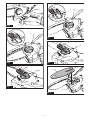
1. Pull the lever up.
►Fig.6: 1. Lever
2. Turn the lever counterclockwise until the sprocket
covercomeso.
►Fig.7: 1. Sprocket cover 2. Lever
3. Remove the sprocket cover then remove the saw
chain and guide bar from the tool body.
Installing the saw chain
To install the saw chain, perform the following steps:
1. Pull the lever up.
►Fig.8: 1. Lever
2. Turn the lever counterclockwise until the sprocket
covercomeso.
►Fig.9: 1. Lever 2. Sprocket cover
3. Remove the sprocket cover.

14 ENGLISH
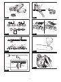
4. Align the hole on the guide bar with the pin on the
tool body, and then place the guide bar as shown in the
gure.
►Fig.10: 1. Guide bar 2. Hole 3. Pin
5. Slide the guide bar toward the sprocket to lock the
pin.
►Fig.11: 1. Guide bar 2. Pin
6. Remove the guide bar from the tool body.
7. Check the direction of the saw chain. Match the
direction of the saw chain with that of the mark on the
tool body.
►Fig.12: 1. Mark on tool body
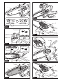
8. Fit one end of the saw chain on the top of the
guide bar.
9. Fit the other end of the saw chain around the
sprocket, then attach the guide bar to the tool body so
that the hole on the guide bar is aligned with the pin on
the body.
►Fig.13: 1. Sprocket
Press the guide bar against the tool body to release the
pin.Thesawchaintensionisautomaticallyadjusted.
►Fig.14: 1. Saw chain 2. Pin 3. Sprocket
10. Place the sprocket cover so that the bolt and pin
on the tool body meet their counterparts on the sprocket
cover.
►Fig.15: 1. Sprocket cover 2. Bolt 3. Pin
11. Turn the lever clockwise until the sprocket cover is
secured then return it to the original position.
►Fig.16: 1. Lever 2. Sprocket cover
Make sure that the saw chain does not loose and the
saw chain can be moved smoothly back and forth. If
necessary,adjustthetensionofthesawchainbyrefer-
ringtothesectionforadjustingsawchaintension.
Adjusting saw chain tension
CAUTION: A chain which is too loose can
jump o the bar and it may cause an injury or
accident.
The saw chain may become loose after many hours
of use. From time to time check the saw chain tension
before use.
Ifthesawchainisloose,adjustthesawchaintension.
1. Pull the lever up.
►Fig.17: 1. Lever
2. Turn the lever counterclockwise a little to loosen
thesprocketcoverlightly.Thechaintensionisadjusted
automatically.
►Fig.18: 1. Sprocket cover 2. Lever
3. Turn the lever clockwise until the sprocket cover is
secured then return it to the original position.
►Fig.19: 1. Lever 2. Sprocket cover
OPERATION
Lubrication
CAUTION:
Do not operate the tool when the tank is
empty. Replenish the oil in due time before the tank is empty.
CAUTION: Prevent the oil from coming into
contact with the skin and eyes. Contact with the
eyes causes irritation. In the event of eye contact,
ush the aected eye immediately with clear
water, then consult a doctor at once.
CAUTION:
Never use waste oil. Waste oil contains
carcinogenic substances. The contaminants in waste
oil cause accelerated wear of the oil pump, the bar and
the chain. Waste oil is harmful to the environment.
NOTICE: When the tool is used for the rst time,
it may take up to two minutes for the saw chain oil
to begin its lubricating eect upon the saw mech-
anism. Run the saw without load until it does so.
NOTICE:
When lling the chain oil for the rst time,
or relling the tank after it has been completely emp-
tied, add oil up to the bottom edge of the ller neck.
The oil delivery may otherwise be impaired.
NOTICE:
Use the saw chain oil exclusively for
Makita tools or equivalent oil available in the market.
NOTICE: Never use oil including dust and parti-
cles or volatile oil.
NOTICE: When pruning trees, use botanical oil.
Mineral oil may harm trees.
NOTICE: Before the cutting operation, make sure
that the provided oil tank cap is screwed in place.
Saw chain is automatically lubricated when the tool is in
operation. Check the amount of remaining oil in the oil
tank periodically through the oil inspection window.
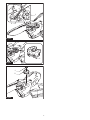
►Fig.20: 1. Oil inspection window 2. Oil tank cap
Tolltheoil,performthefollowingsteps:
1. Clean the area around the oil tank cap thoroughly
to prevent any dirt from entering the oil tank.
2. Lay the tool on its side.
3. Push the button on the oil tank cap so that the
button on the other side stands up, and then remove the
oil tank cap by turning it.
►Fig.21: 1. Oil tank cap 2. Tighten 3. Loosen
4.
Fill the oil tank with the oil. The proper amount of oil is 55 ml.
5. Screwtheoiltankcaprmlybackinplace.
6. Wipe away any spilt chain oil carefully.
NOTE:Ifitisdiculttoremovetheoiltankcap,insert
the tip of slotted screwdriver into the slot of the oil
tank cap, and then remove the oil tank cap by turning
it counterclockwise.
►Fig.22: 1. Slot 2. Slotted screwdriver
Afterrelling,holdthetoolawayfromthematerialto
be cut. Start it and wait until lubrication on saw chain is
adequate.
►Fig.23

15 ENGLISH
Working with the tool
CAUTION: Keep all parts of the body away
from the saw chain when the tool is operating.
CAUTION: Hold the tool rmly with both
hands when the tool is operating.
CAUTION: Do not overreach. Keep proper
footing and balance at all times.
NOTICE: Never toss or drop the tool.
NOTICE: Do not cover the vents of the tool.
Before starting the tool, bring the root of guide bar and
the support part of tool body in contact with the branch to
becutasshowninthegure.Whilecontactingthebranch
with the tool and guide bar, start the tool and saw the
branch by moving the tool down along the branch.
►Fig.24
CAUTION: Before the cutting operation, make
sure that the branch to be cut is in contact with
the root of guide bar and the support part of tool
body. Otherwise, the tool may be pulled toward the
tip of guide bar and the guide bar may wobble, and
mayresultinaninjury.
Carrying tool
Before carrying the tool, always remove the battery
cartridge from the tool. Then attach the guide bar cover.
Also cover the battery cartridge with the battery cover.
►Fig.25: 1. Guide bar cover 2. Battery cover
MAINTENANCE
CAUTION:
Always be sure that the tool is switched
o and the battery cartridge is removed before attempt-
ing to perform inspection or maintenance.
CAUTION: Always wear gloves when perform-
ing any inspection or maintenance.
NOTICE: Never use gasoline, benzine, thinner,
alcohol or the like. Discoloration, deformation or
cracks may result.
To maintain product SAFETY and RELIABILITY,
repairs,anyothermaintenanceoradjustmentshould
be performed by Makita Authorized or Factory Service
Centers, always using Makita replacement parts.
Sharpening the saw chain
Sharpen the saw chain when:
•
Mealy sawdust is produced when damp wood is cut;
• Thechainpenetratesthewoodwithdiculty,even
when heavy pressure is applied;
• The cutting edge is obviously damaged;
• The saw pulls to the left or right in the wood.
(caused by uneven sharpening of the saw chain or
damage to one side only)
Sharpen the saw chain frequently but a little each time.
Twoorthreestrokeswithaleareusuallysucientfor
routine resharpening. When the saw chain has been
resharpened several times, have it sharpened in our
authorized service center.
Sharpening criteria:
WARNING: An excessive distance between
the cutting edge and depth gauge increases the
risk of kickback.
►Fig.26: 1. Cutter length 2. Distance between cutting
edge and depth gauge 3. Minimum cutter
length (3 mm)
— Allcutterlengthmustbeequal.Dierentcutter
lengths prevent the saw chain from running
smoothly and may cause the saw chain to break.
— Do not sharpen the chain when the cutter length
has reached 3 mm or shorter. The chain must be
replaced with new one.
— The chip thickness is determined by the distance
between the depth gauge (round nose) and the
cutting edge.
— The best cutting results are obtained with following
distance between cutting edge and depth gauge.
• Chain blade 80TXL : 0.65 mm
►Fig.27
— The sharpening angle of 30° must be the same on
allcutters.Dierentcutteranglescausethechain
to run roughly and unevenly, accelerate wear, and
lead to chain breaks.
— Useasuitableroundlesothatthepropersharp-
ening angle is kept against the teeth.
• Chain blade 80TXL : 55°
File and le guiding
— Useaspecialroundle(optionalaccessory)for
saw chains to sharpen the chain. Normal round
lesarenotsuitable.
— Diameteroftheroundleforeachsawchainisas
follows:
• Chain blade 80TXL : 4.0 mm
—
Theleshouldonlyengagethecutterontheforward
stroke.Lifttheleothecutteronthereturnstroke.
— Sharpentheshortestcutterrst.Thenthelength
of this shortest cutter becomes the standard for all
other cutters on the saw chain.
— Guidetheleasshowninthegure.
►Fig.28: 1. File 2. Saw chain
— Thelecanbeguidedmoreeasilyifaleholder
(optionalaccessory)isemployed.Theleholder
has markings for the correct sharpening angle of
30° (align the markings parallel to the saw chain)
and limits the depth of penetration (to 4/5 of the
lediameter).
►Fig.29: 1. File holder
— After sharpening the chain, check the height of the
depth gauge using the chain gauge tool (optional
accessory).
►Fig.30
— Removeanyprojectingmaterial,howeversmall,
withaspecialatle(optionalaccessory).
— Roundothefrontofthedepthgaugeagain.

16 ENGLISH
Cleaning the guide bar
Chips and sawdust will build up in the guide bar groove.
Theymayclogthebargrooveandimpairtheoilow.
Clean out the chips and sawdust every time when you
sharpen or replace the saw chain.
►Fig.31
Cleaning the sprocket cover
Chips and saw dust will accumulate inside of the
sprocket cover. Remove the sprocket cover and saw
chain from the tool then clean the chips and saw dust.
►Fig.32
Cleaning the oil discharge hole
Small dust or particles may be built up in the oil discharge
hole during operation. These dust or particles may impair the
oiltoowandcauseaninsucientlubricationonthewhole
saw chain. When a poor chain oil delivery occurs at the top of
guide bar, clean the oil discharge hole as follows.
1.
Remove the sprocket cover and saw chain from the tool.
2. Remove the small dust or particles using a slotted
screwdriver or the like.
►Fig.33: 1. Slotted screwdriver 2. Oil discharge hole
3. Insert the battery cartridge into the tool. Pull the
switchtriggertoowbuilt-updustorparticlesotheoil
discharge hole by discharging chain oil.
4. Remove the battery cartridge from the tool.
Reinstall the sprocket cover and saw chain and guide
bar on the tool.
Replacing the sprocket
CAUTION: A worn sprocket will damage a
new saw chain. Have the sprocket replaced in this
case.
Beforettinganewsawchain,checktheconditionof
the sprocket.
►Fig.34: 1. Sprocket 2. Areas to be worn out
Alwaystanewlockingringwhenreplacingthe
sprocket.
►Fig.35: 1. Locking ring 2. Sprocket
NOTICE: Make sure that the sprocket is installed
as shown in the gure.
Storing the tool
1. Clean the tool before storing. Remove any chips
and sawdust from the tool after removing the sprocket
cover.
2. After cleaning the tool, run it under no load to lubri-
cate the saw chain and guide bar.
3. Cover the guide bar with the guide bar cover.
4. Empty the oil tank.
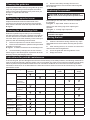
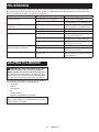
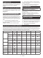
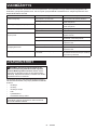
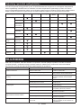
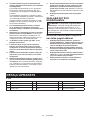
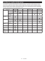
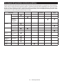
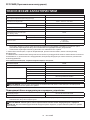
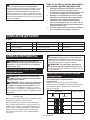
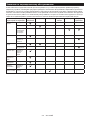
Instructions for periodic maintenance
To ensure long life, prevent damage and ensure the full functioning of the safety features, the following maintenance
must be performed regularly. Warranty claims can be recognized only if this work is performed regularly and properly.
Failure to perform the prescribed maintenance work can lead to accidents! The user of the tool must not perform
maintenance work which is not described in the instruction manual. All such work must be carried out by our autho-
rized service center.
Check item / Operating time Before
operation
Everyday Every week Every 3
month
Annually Before
storage
Whole tool Inspection. -----
Cleaning. -----
Check at
authorized
service center.
----
Saw chain Inspection. -----
Sharpening if
necessary.
-----
Guide bar Inspection. ----
Remove from
the tool.
-----
Chain
lubrication
Check the oil
feed rate.
-----
Switch trigger Inspection. -----
Lock-olever Inspection. -----
Oil tank cap Check
tightness.
-----
Screws and
nuts
Inspection. - - ---

17 ENGLISH
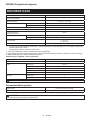
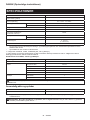
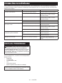
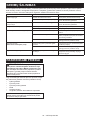
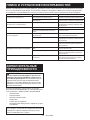
TROUBLESHOOTING
Beforeaskingforrepairs,conductyourowninspectionrst.Ifyoundaproblemthatisnotexplainedinthemanual,
do not attempt to dismantle the tool. Instead, ask Makita Authorized Service Centers, always using Makita replace-
ment parts for repairs.
Malfunction status Cause Action
The tool does not start. Battery cartridge is not installed. Install a charged battery cartridge.
Battery problem (low voltage). Recharge the battery cartridge. If recharg-
ingisnoteective,replacethebattery
cartridge.
The motor stops running after a little use. Battery's charge level is low. Recharge the battery cartridge. If recharg-
ingisnoteective,replacethebattery
cartridge.
No oil on the chain. Oil tank is empty. Fill the oil tank.
Oil guide groove is dirty. Clean the groove.
The tool does not reach maximum RPM. Battery cartridge is installed improperly. Install the battery cartridge as described in
this manual.
Battery power is dropping. Recharge the battery cartridge. If recharg-
ingisnoteective,replacethebattery
cartridge.
The drive system does not work correctly. Ask the authorized service center in your
region for repair.
Abnormal vibration:
Stop the tool immediately!
Loose guide bar or saw chain. Adjusttheguidebarandsawchain
tension.
Tool malfunction. Ask the authorized service center in your
region for repair.
The saw chain cannot be installed. The combination of saw chain and
sprocket is not correct.
Use the correct combination of saw chain
and sprocket by referring to the section for
specications.
OPTIONAL
ACCESSORIES
CAUTION: These accessories or attachments
are recommended for use with your Makita tool
specied in this manual. The use of any other
accessories or attachments might present a risk of
injurytopersons.Onlyuseaccessoryorattachment
for its stated purpose.
If you need any assistance for more details regard-
ing these accessories, ask your local Makita Service
Center.
• Saw chain
• Guide bar
• Guide bar cover
• File
• Tool bag
• Makita genuine battery and charger
NOTE: Some items in the list may be included in the
tool package as standard accessories. They may
dierfromcountrytocountry.

18 SVENSKA
SVENSKA (Originalinstruktioner)
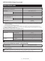
SPECIFIKATIONER
Modell: UC100D
Total längd
(utan svärd och batteri)
350 mm
Märkspänning 10,8 V - 12 V likström max
Nettovikt *1 1,0 kg
*2 1,5 - 1,6 kg
Standard svärdlängd 100 mm
Rekommenderad svärdlängd 100 mm
Appliceradsågkedjetyp
(se tabellen nedan)
80TXL
Kedjehjul Antal tänder 7
Delning 0,325″
Kedjehastighet 0 - 8,0 m/s
(0 - 480 m/min)
Tankvolymkedjeolja 55 cm3
• Pågrundavvårtpågåendeprogramförforskningochutvecklingkandessaspecikationerändrasutanföregå-
ende meddelande.
• Specikationerkanvarieramellanolikaländer.
*1:Vikt,utansågkedjan,svärdet,svärdskyddet,oljanochbatterikassetten/kassetterna.
*2: Den lättaste och tyngsta viktkombinationen enligt EPTA-procedur 01/2014. Vikten kan variera beroende på tillbe-
höret/tillbehören, inklusive batterikassetten/kassetterna.
Kombination av sågkedja, svärd och kedjehjul
Såpgkedjetyp 80TXL
Antal drivlänkar 26
Svärd Svärdlängd 100 mm
Såglängd 111 mm
Delning 0,325″
Spårvidd 1,1 mm
Typ Solitt svärd
Kedjehjul Antal tänder 7
Delning 0,325″
VARNING:Användenlämpligkombinationavsvärdochsågkedje.Iannatfallkanpersonskadauppstå.
Tillgänglig batterikassett och laddare
Batterikassett BL1016 / BL1021B / BL1041B
Laddare DC10SA / DC10SB / DC10WC / DC10WD / DC18RE
• Vissaavbatterikassetternaochladdarnapålistanovankanskeintennstillgängligaidinregion.
VARNING: Använd endast batterikassetter och laddare från listan ovan. Användning av andra batterikas-
setter och laddare kan orsaka personskada och/eller brand.

19 SVENSKA
Symboler
Följandevisarsymbolernasomkananvändasförutrust-
ningen. Se till att du förstår innebörden innan användning.
Läs igenom bruksanvisningen.
Använd skyddsglasögon och hörselskydd.
Använd alltid två händer vid användning
av verktyget.
Se upp med bakåtkast och undvik kontakt
med svärdets spets.
Utsätt inte verktyget för fukt.
Maximal tillåten kaplängd
Kedjansrotationsriktning
Ni-MH
Li-ion
Gäller endast inom EU
P.g.a. förekomsten av farliga komponenter
i utrustningen kan avfall innehållande
elektrisk och elektronisk utrustning, acku-
mulatorer och batterier ha negativ inverkan
påmiljönochmänniskorshälsa.
Kassera inte elektriska och elektroniska appa-
rater eller batterier ihop med hushållsavfall!
I enlighet med EU-direktiven om avfall som
utgörs av eller innehåller elektrisk och elektro-
nisk utrustning och om batterier och ackumula-
torer och förbrukade batterier och ackumulato-
rer, och dess införlivande i nationell lagstiftning,
bör förbrukad elektrisk och elektronisk
utrustning, batterier och ackumulatorer förvaras
separat och transporteras till en särskild upp-
samlingsplats för kommunalt avfall, som drivs i
enlighetmedregelverketförmiljöskydd.
Detta anges av symbolen med den över-
kryssadesoptunnanpåhjulsomsitterpå
utrustningen.
Garanteradljudeektnivåenligt
EU-direktivet för utomhusbuller.
LjudeektnivåenligtAustraliaNSWNoise
Control Regulation (Bullerreglering)
Avsedd användning
Verktyget är avsett för att såga grenar på träd eller
buskarmedhjälpavensågkedja.
Buller
Den normala bullernivån för A-belastning är bestämd
enligt EN62841-4-1:
Ljudtrycksnivå(LpA) : 76 dB (A)
Ljudeektnivå(LWA) : 87 dB (A)
Mättolerans (K): 3 dB (A)
OBS: Det deklarerade bullervärdet har uppmätts i
enlighet med standardtestmetoden och kan användas
förjämförandetavenmaskinmedenannan.
OBS: Det deklarerade bulleremissionsvärdet kan
också användas i en preliminär bedömning av expo-
nering för vibration.
VARNING: Använd hörselskydd.
VARNING: Bulleremissionen under faktisk
användning av maskinen kan skilja sig från det
deklarerade värdet, beroende på hur maskinen
används och särskilt vilken typ av arbetsstycke
som behandlas.
VARNING: Var noga med att identiera säker-
hetsåtgärder för att skydda användaren, vilka är
grundade på en uppskattning av graden av expo-
nering för vibrationer under de faktiska använd-
ningsförhållandena, (ta, förutom avtryckartiden,
med alla delar av användarcykeln i beräkningen,
som till exempel tiden då maskinen är avstängd
och när den går på tomgång).
Vibration
Det totala vibrationsvärdet (treaxlad vektorsumma)
bestämt enligt EN62841-4-1:
Arbetsläge: sågning i trä
Vibrationsemission (ah,W) : 4,8 m/s2
Mättolerans (K): 1,5 m/s2
OBS:
Det deklarerade totala vibrationsvärdet har
uppmätts i enlighet med standardtestmetoden och kan
användasförjämförandetavenmaskinmedenannan.
OBS: Det deklarerade totala vibrationsvärdet kan
också användas i en preliminär bedömning av expo-
nering för vibration.
VARNING: Vibrationsemissionen under fak-
tisk användning av maskinen kan skilja sig från
det deklarerade värdet, beroende på hur maski-
nen används och särskilt vilken typ av arbetss-
tycke som behandlas.
VARNING: Var noga med att identiera säker-
hetsåtgärder för att skydda användaren, vilka är
grundade på en uppskattning av graden av expo-
nering för vibrationer under de faktiska använd-
ningsförhållandena, (ta, förutom avtryckartiden,
med alla delar av användarcykeln i beräkningen,
som till exempel tiden då maskinen är avstängd
och när den går på tomgång).
Försäkran om överensstämmelse
Gäller endast inom EU
Försäkran om överensstämmelse ingår i bilaga A till
denna bruksanvisning.
SÄKERHETSVARNINGAR
Allmänna säkerhetsvarningar för
maskiner
VARNING Läs alla säkerhetsvarningar, instruk-
tioner, illustrationer och specikationer som
medföljer detta elverktyg.Underlåtenhetattföljaalla
instruktioner nedan kan leda till elstötar, brand och/eller
allvarliga personskador.

20 SVENSKA
Spara alla varningar och instruk-
tioner för framtida referens.
Termen ”maskin” som anges i varningarna hänvisar till
din eldrivna maskin (sladdansluten) eller batteridrivna
maskin (sladdlös).
Allmänna säkerhetsvarningar för
grensåg
1. Håll alla kroppsdelar borta från sågkedjan när
grensågen är i drift. Se till att sågkedjan inte
vidrör någonting innan du startar grensågen.
Ett ögonblick av ouppmärksamhet medan du arbe-
tar med grensågen kan leda till att den kommer i
kontakt med dina kläder eller med kroppen.
2. Håll alltid grensågen med en hand på det
bakre handtaget och den andra handen på
stödhandtaget.
3. Håll grensågen endast i de isolerade handta-
gen eftersom sågkedjan kan komma i kontakt
med en dold elkabel.Omsågkedjankommeri
kontakt med en strömförande ledning blir grenså-
gens blottlagda metalldelar strömförande och kan
ge operatören en elektrisk stöt.
4. Använd ögonskydd. Ytterligare skyddsutrust-
ning i form av hörselskydd samt för huvud,
händer, ben och fötter rekommenderas.
Passande utrustning minskar risken för person-
skadorfrånygandematerialresterelleroavsiktlig
kontaktmedsågkedjan.
5. Arbeta inte med grensågen i ett träd, på en
stege, på ett tak eller något annat ostadigt
underlag. Att arbeta med en grensåg på det sättet
kan leda till allvarlig personskada.
6. Stå alltid stadigt och arbeta endast med gren-
sågen när du står på ett fast, säkert och plant
underlag. Hala eller instabila ytor kan göra att du
tappar balansen eller kontrollen över grensågen.
7. Var uppmärksam vid sågning av en gren som
är spänd eftersom den kan fjädra tillbaka. När
spänningeniträbrernasläpperkandenspända
grenen slå tillbaka mot användaren och/eller slå
grensågen ur händerna.
8. Var mycket försiktig vid sågning av buskar och
unga träd.Detnamaterialetkanfångasågked-
janochpiskasemotdigellerfådigurbalans.
9. Bär grensågen med grensågen avstängd och
borta från kroppen. Vid transport eller förva-
ring av grensågen ska alltid svärdskyddet sitta
på. Korrekt hantering av grensågen minskar ris-
kenföroavsiktligkontaktmedsågkedjannärden
är i rörelse.
10. Följ instruktionerna för smörjning, ked-
jesträckning och utbyte av svärdet och kedjan.
Felaktigsträckningellerkedjesmörjningkan
antingenfåkedjanattgåavellerökariskenför
bakåtkast.
11. Såga endast i trä. Använd endast grensågen
för det ändamål den är avsedd för. Använd till
exempel inte grensågen för sågning i metall,
plast, murverk eller annat byggmaterial som
inte är av trä. Användning av grensågen för annat
ändamål än vad den är avsedd för kan leda till att
en farlig situation uppstår.
12. Denna grensåg är inte avsedd för trädfällning.
Användning av grensågen för annat ändamål än
vad den är avsedd för kan leda till allvarliga per-
sonskador på användaren eller åskådare.
13. Följ alla instruktioner när du tar bort material
som fastnat, tar grensågen i förvar eller servar
den. Säkerställ att strömbrytaren är avstängd
samt att batteripaketet är avlägsnad.
14.
Orsaker till och förebyggande av bakåtkast:
Bakåtkast kan uppstå när nosen eller spetsen på
svärdetkommerikontaktmedettobjekt,ellernär
träetknipertagiochlåserfastkedjesågeniskäret.
Kontakt med spetsen kan i vissa fall orsaka en
plötslig motsatt reaktion där svärdet slås uppåt
och bakåt mot användaren.
Fastlåsningavsågkedjanlängsspetsenpåsvärdet
kan snabbt trycka svärdet bakåt mot användaren.
Endera av dessa reaktioner kan göra att du tappar
kontrollen över sågen vilket kan resultera i allvarliga
personskador. Lita inte uteslutande på de inbyggda
säkerhetsanordningarna i din såg. Som en grensågs-
användare ska du vidta försiktighetsåtgärder så att
inte olyckor eller skador uppstår under sågarbetet.
Bakåtkast beror på ovarsamhet med grensågen
och/eller felaktiga arbetsrutiner eller -förhållanden
och kan undvikas genom att vidta korrekta nedan-
stående försiktighetsåtgärder:
• Upprätthåll ett stadigt grepp med tummar
och ngrar runt grensågens handtag,
med båda händerna på sågen och i en
position där din kropp och dina armar kan
undvika styrkan av ett eventuellt bakåt-
kast. Användaren kan kontrollera krafterna i
ett bakåtkast om lämpliga försiktighetsåtgär-
der vidtas. Släpp inte grensågen.
►Fig.1
• Sträck dig inte för långt och såga inte
över axelhöjd. Detta förhindrar oavsiktlig
kontakt med spetsen och ger bättre kontroll
över grensågen i oväntade situationer.
• Använd endast sådana reservsvärd och
reservsågkedjor som specicerats av
tillverkaren. Felaktiga reservsvärd och
reservsågkedjorkanorsakaattkedjangårav
och/eller bakåtkast.
• Följ tillverkarens instruktioner för
slipning och underhåll av sågkedjan.
Minskningavhöjdenpåunderställnings-
klacken kan leda till ökad risk för bakåtkast.
15. Följ alla instruktioner när du tar bort material
som fastnat, tar grensågen i förvar eller servar
den. Säkerställ att strömbrytaren är avstängd
samt att batteripaketet är avlägsnad.
Ytterligare säkerhetsinstruktioner
Personlig skyddsutrustning
1. Använd åtsittande kläder som inte begränsar
rörligheten.
2. Följandeskyddskläderärlämpligaunderarbete:
• Godkändskyddshjälmsomskyddmotned-
fallande grenar o dyl.
• Visir eller skyddsglasögon.
• Hörselskydd (hörselkåpor eller öronproppar).
Frekvensanalys kan erhållas på begäran.
Sidan laddas ...
Sidan laddas ...
Sidan laddas ...
Sidan laddas ...
Sidan laddas ...
Sidan laddas ...
Sidan laddas ...
Sidan laddas ...
Sidan laddas ...
Sidan laddas ...
Sidan laddas ...
Sidan laddas ...
Sidan laddas ...
Sidan laddas ...
Sidan laddas ...
Sidan laddas ...
Sidan laddas ...
Sidan laddas ...
Sidan laddas ...
Sidan laddas ...
Sidan laddas ...
Sidan laddas ...
Sidan laddas ...
Sidan laddas ...
Sidan laddas ...
Sidan laddas ...
Sidan laddas ...
Sidan laddas ...
Sidan laddas ...
Sidan laddas ...
Sidan laddas ...
Sidan laddas ...
Sidan laddas ...
Sidan laddas ...
Sidan laddas ...
Sidan laddas ...
Sidan laddas ...
Sidan laddas ...
Sidan laddas ...
Sidan laddas ...
Sidan laddas ...
Sidan laddas ...
Sidan laddas ...
Sidan laddas ...
Sidan laddas ...
Sidan laddas ...
Sidan laddas ...
Sidan laddas ...
Sidan laddas ...
Sidan laddas ...
Sidan laddas ...
Sidan laddas ...
Sidan laddas ...
Sidan laddas ...
Sidan laddas ...
Sidan laddas ...
Sidan laddas ...
Sidan laddas ...
Sidan laddas ...
Sidan laddas ...
Sidan laddas ...
Sidan laddas ...
Sidan laddas ...
Sidan laddas ...
Sidan laddas ...
Sidan laddas ...
Sidan laddas ...
Sidan laddas ...
Sidan laddas ...
Sidan laddas ...
Sidan laddas ...
Sidan laddas ...
Sidan laddas ...
Sidan laddas ...
Sidan laddas ...
Sidan laddas ...
Sidan laddas ...
Sidan laddas ...
Sidan laddas ...
Sidan laddas ...
Sidan laddas ...
Sidan laddas ...
Sidan laddas ...
Sidan laddas ...
-
 1
1
-
 2
2
-
 3
3
-
 4
4
-
 5
5
-
 6
6
-
 7
7
-
 8
8
-
 9
9
-
 10
10
-
 11
11
-
 12
12
-
 13
13
-
 14
14
-
 15
15
-
 16
16
-
 17
17
-
 18
18
-
 19
19
-
 20
20
-
 21
21
-
 22
22
-
 23
23
-
 24
24
-
 25
25
-
 26
26
-
 27
27
-
 28
28
-
 29
29
-
 30
30
-
 31
31
-
 32
32
-
 33
33
-
 34
34
-
 35
35
-
 36
36
-
 37
37
-
 38
38
-
 39
39
-
 40
40
-
 41
41
-
 42
42
-
 43
43
-
 44
44
-
 45
45
-
 46
46
-
 47
47
-
 48
48
-
 49
49
-
 50
50
-
 51
51
-
 52
52
-
 53
53
-
 54
54
-
 55
55
-
 56
56
-
 57
57
-
 58
58
-
 59
59
-
 60
60
-
 61
61
-
 62
62
-
 63
63
-
 64
64
-
 65
65
-
 66
66
-
 67
67
-
 68
68
-
 69
69
-
 70
70
-
 71
71
-
 72
72
-
 73
73
-
 74
74
-
 75
75
-
 76
76
-
 77
77
-
 78
78
-
 79
79
-
 80
80
-
 81
81
-
 82
82
-
 83
83
-
 84
84
-
 85
85
-
 86
86
-
 87
87
-
 88
88
-
 89
89
-
 90
90
-
 91
91
-
 92
92
-
 93
93
-
 94
94
-
 95
95
-
 96
96
-
 97
97
-
 98
98
-
 99
99
-
 100
100
-
 101
101
-
 102
102
-
 103
103
-
 104
104


Makita UC100D Användarmanual
- Kategori
- Kraft motorsågar
- Typ
- Användarmanual
på andra språk
- eesti: Makita UC100D Kasutusjuhend
- English: Makita UC100D User manual
- dansk: Makita UC100D Brugermanual
Relaterade papper
Andra dokument
-
DeWalt DCMPS520N Användarmanual
-
Stanley SFMCPS415D1 Användarmanual
-
FLORABEST FHEHS 900 A1 Bruksanvisning
-
STIHL HTA 66, 86 Användarmanual
-
-
STIHL GTA 26 Användarmanual
-
-
BLACK+DECKER BCASK61D Användarmanual
-
AL-KO MT 36 Li Användarmanual
-
BLACK+DECKER PS7525 T1 Bruksanvisning