
Owner’s Manual
Bedienungsanleitung
Mode d’emploi

1
Contents
The G1D is a high-performance guitar synthesizer
pickup/driver designed for use with the Yamaha G50
Guitar MIDI Converter. When properly installed and
adjusted it can add high-performance MIDI guitar
synthesizer capability to just about any electric or
steel-string acoustic guitar.
Please read this owner’s manual carefully, and
follow the installation instructions within in order to
ensure proper operation.
Precautions .................. 2
Nomenclature ................ 3
Installation .................. 4
Setup ..................... 12
Specifications ................ 14

2
Precautions
Precautions !! PLEASE READ THIS BEFORE PROCEEDING !!
■ Handling and Transport
• Never apply excessive force to the controls,
connectors or other parts of the instrument.
• Physical shocks caused by dropping, bumping,
or placing heavy objects on the instrument can
result in scratches and more serious damage.
• Be careful not to damage the G1D controller
when placing the guitar in a case or on a stand.
■ Cleaning
• Clean the unit with a dry soft cloth.
• A slightly damp cloth may be used to remove
stubborn grime and dirt.
• Never use cleaners such as alcohol or thinner.
■ Service and Modification
• The G1D contains no user serviceable parts.
Opening it or tampering with it in any way can
lead to irreparable damage and possibly
electric shock. Refer all servicing to qualified
YAMAHA personnel.
■ Location
Do not expose the G1D to the following conditions
to avoid deformation, discoloration, or more
serious damage.
• Direct sunlight (e.g. near a window).
• High temperatures (e.g. near a heat source,
outside, or in a car during the daytime).
• Excessive humidity.
• Excessive dust.
• Strong vibration.
■ Connections
• When connecting the G1D to the Yamaha G50
Guitar MIDI Converter, be sure to use the
specified multi-pin cable (supplied with the
G50 Guitar MIDI Converter).
• Always connect the direct guitar cable (page
12), even if you don’t intend to use the direct
guitar sound. The direct guitar cable is essential
for proper grounding, to minimize noise and
prevent electric shock.
• Always unplug cables by gripping the plug
firmly, not by pulling on the cable.
• Disconnect all cables before moving the
instrument or any connected equipment.
YAMAHA is not responsible for damage caused by improper installation, handling, or operation.

3
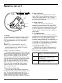
Nomenclature
Nomenclature
1 Pickup
This is the actual “pickup” unit which converts
the physical motion of the guitar’s strings into an
electrical signal which can be processed by the
G1D and transmitted to the G50 Guitar MIDI
Converter.
■ CAUTION!
• Because of its slender dimensions the pickup
unit is quite delicate and can be damaged if sub-
jected to unnecessary force, bending, or twisting.
Handle the pickup carefully!
2 Multi-pin Cable Connector
This is the main output from the G1D. One end
of the multi-pin cable supplied with the G50 Guitar
MIDI Converter is plugged in here, and the other
end of the cable is plugged into the DIVIDED
INPUT connector on the G50. The multi-pin cable
connector delivers both the individual string output
from the G1D pickup and the combined output
from the guitar’s output jack to the G50 Guitar
MIDI Converter. It also supplies power from the
G50 to the G1D, and sends the control signals
produced by the G1D UP/DOWN buttons and
VOL control to the G50.
3 Direct Guitar Input Jack
This jack receives the combined output from
the guitar’s normal pickups from the guitar’s output
jack. The short cable supplied with the G1D is
used to connect the guitar’s output jack (large 1/4"
phone jack end of the cable) to the G1D direct
guitar input jack (small mini-jack end of the cable).
7
1
2
3
4
5
6
4 Power Indicator
The G1D is receiving power from the G50
Guitar MIDI Converter when this indicator is lit.
The indicator lights when the G1D is properly
connected to the G50 via the multi-pin cable, and
the G50 power is turned ON.
5 Volume Control
Controls the volume of the MIDI tone
generator(s) connected to the G50 Guitar MIDI
Converter (the G50 translates the position of this
control to MIDI master volume data which is sent
to the tone generator). Use the guitar’s original
volume controls to adjust the volume of the direct
guitar sound.
6 UP/DOWN Buttons
These button can be used to select different
synthesizer voices and select other functions while
playing the G1D. Press either button briefly to
increment or decrement the G50 Guitar MIDI
Converter memory number by one (and thereby the
voice number of the synthesizer or tone generator
it is driving), or hold either button for continuous
scrolling in the corresponding direction.
7 GUITAR/MIX/SYNTH Selector
Selects the type of output to be delivered via
the multi-pin cable connector to the G50 Guitar
MIDI Converter, as listed below:
GUITAR Only the direct guitar sound will be
heard (i.e. no synthesizer sound will be
produced).
MIX Both the direct guitar sound and
individual-string synthesizer output
will be heard.
SYNTH Only the individual-string synthesizer
output is sent to the G50 (no direct
guitar sound will be heard).

4
Installation
Installation
Guitar Compatibility
The G1D can be installed on most electric and
steel-string acoustic guitars, with the following
exceptions:
• Since the G1D employs a magnetic pickup, it
will not work with nylon or other non-metallic
strings.
• The G1D is designed for use with 6-string
guitars. It will not work properly with 12-string
guitars or other non-standard string configura-
tions.
• The G1D pickup should be installed between
the guitar’s bridge and bridge pickup. Installa-
tion may not be possible if there is not enough
room between the bridge and bridge pickup of
your guitar, or between the guitar top and
strings.
Installing the Controller
Unit
Install the controller unit before installing the
pickup, being careful not to damage the pickup
during the installation process.
A number of installation options are provided:
• Screw.
• Double-sided adhesive tape.
• Re-usable adhesive pads.
• Velcro fastener.
• Bracket.
• Suction cups.
Choose the method which best is best suited to
your guitar and playing requirements.
Installing the G1D on a guitar is not a
difficult process, but it does require care and at
least a modicum of mechanical ability. If you
don’t feel totally confident that you can handle
the job, it might be a good idea to leave the
installation to someone experienced in guitar
modification or repair.
IMPORTANT!
Make sure your guitar’s neck (truss rod) and
string height/intonation (bridge) are properly
adjusted before installing the G1D.

5
Installation
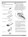
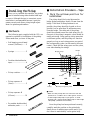
■ Hardware
The following parts are provided for installation
of the controller unit. Please make sure you have
all the parts.
• Self-tapping round-head screw (3x16mm)
...........................1
• Double-sided adhesive tape....................3
• Re-usable double-sided adhesive pads
(transparent). .....3
• Spacer (double-sided adhesive). ............6
• Velcro fastener.........................................1
• Bracket.....................................................1
• Suction cups ............................................3
Controller
Pickup
Multi-pin cable
GUITAR
MIX
SYNTH
UP
DOWN
VOL
Direct guitar’s cable
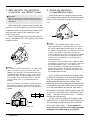
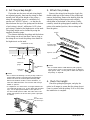
■ Installation Procedure
1. Determine the optimum
location for installation.
Normally, the controller should be attached
somewhere behind the guitar’s bridge, as shown in
the illustration. It should be accessible, but it
should not interfere with your playing or any of the
guitars controls or adjustments. Consider the
following points carefully when deciding on the
best location to install the controller:
• The controller and pickup cable should not get
in the way of your picking-hand at any time.
Make sure the location you choose will not
affect your playing style.
• The controller should not block or hamper
access to any of the guitar’s controls: tone,
volume, bridge adjustments (especially watch
out for intonation/saddle screws accessed from
the rear of the bridge).
• The controller must be well within reach of
both the pickup cable (when the pickup is in its
final installed position) and the direct guitar
cable
• Neither the controller unit itself nor any of the
connected cable plugs should extend beyond the
body of the guitar to prevent accidental damage.

6
3. Attach the controller.
(screw/adhesive tape)
Remove the protective backing from one side
of the adhesive tape patches and attach them to the
bottom of the controller as shown in the illustra-
tion.
■ NOTES
• You can use the standard adhesive tape or the re-
usable adhesive pads on just about any type of guitar.
See “The Re-usable Adhesive Pads” below, for details.
• The adhesive tape/pads may react chemically with the
finish on some guitars, causing discoloration or
otherwise marring the finish. It might be a good idea
to try attaching a small piece of tape/pad at some
location that is not obvious for a few days before
actual installation.
• If your guitar has an arched top or is shaped in such
a way that the controller won’t sit properly with only
the standard adhesive tape, use as many of the
spacers as required in the appropriate location(s) to
position the controller as required. The spacers are
adhesive on both sides, with protective backing like
the standard adhesive tape.
Next, carefully clean the area on the guitar body
to which the controller is to be attached to eliminate
dust, dirt, and particularly any oil or grease which
might prevent the adhesive from sticking. Then
remove the protective backing from the exposed side
of the adhesive tape, and carefully attach the control-
ler to the guitar making sure that the screw hole in
the controller is perfectly aligned with the screw hole
in the body of your guitar (if you drilled one). Press
firmly — but don’t use excessive force — to ensure
that the tape sticks securely.
Finally, screw the supplied self-tapping round-
head screw (3 x 16 mm) into the pre-drilled hole in
the guitar body through the hole in the controller.
Screw only “finger tight” — if you attempt to
screw the screw in too far or too tight you might
damage the controller and or your guitar!
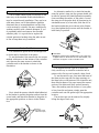
2. Mark and drill the controller
screw hole
(see “NOTES” below).
■ CAUTION!
• Make sure the multi-pin cable and direct guitar's
cable are disconnected from the controller before
installation.
While holding the controller unit in exactly the
position it is to be installed, use a fine pen or scribe
to mark the center of the screw hole (located in the
multi-pin cable recess of the controller) on the
body of your guitar.
Then set the controller unit aside and carefully
drill a 2-millimeter (1/16" inch, approx.) hole at the
marked location.
Installation
screw hole
■ NOTES
• For acoustic or semi-acoustic guitars, or simply if the
idea of drilling a hole in your guitar makes you
shudder, the controller can be attached using only
the adhesive tape, the Velcro faster, or any of the
other installation options described below. Please
note, however, that screw installation is the most
secure method, and is recommended wherever
possible.
• The Velcro fastener is provided for players who will
be frequently removing and reattaching the G1D.
DO NOT use the adhesive pads if you use the Velcro
fastener.
Bottom side

7
The Re-usable Adhesive Pads
The re-usable adhesive pads can be used in the
same way as the standard double-sided adhesive
tape for controller unit installation. They can be re-
used many times, and if their adhesive qualities
deteriorate due to accumulated dust and dirt, they
can be restored to virtually like-new conditions by
washing carefully with a neutral detergent. If you
do repeatedly attach and remove the re-usable
adhesive pads, it is a good idea to replace the
original protective backing when the pads are not
in use to keep them in top condition.
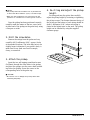
Bracket Installation
This installation option has the advantages that
no holes need to be drilled in the guitar.
To use the bracket, first unscrew the two screws
marked with arrows on the bottom of the controller
unit, then use the same screws to attach the
controller unit to the bracket as shown in the
illustration.
Next, attach the spacers (double-sided adhesive)
to the bracket to protect the guitar surface from the
screw heads, and attach the bracket to the guitar in
the appropriate position, as shown in the illustra-
tion.
An alternative method is to attach the bracket
using the guitar’s strap pin (the spacers should still
be used to prevent the controller/bracket assembly
from scratching the surface of the guitar). Loosen
the strap pin on the guitar body by unscrewing its
attachment screw by a few turns, slide the slot in
the bracket under the pin as shown in the illustra-
tion, then tighten the pin screw until the bracket is
held firmly in position.
■ CAUTION!
• Repeated loosening and tightening of the strap pin,
or application of excessive force to the bracket, can
cause the strap pin screw to become loose.
Suction Cup Installation
The supplied suction cups are a handy and
fairly secure way to attach the controller unit to
guitars with a flat top and a smooth, shiny finish.
To use the suction cups, first insert the bases of
the three suction cups into the large openings in
the three holes on the bottom of the controller unit,
then slide the bases of the cups toward the narrow
section of the holes until they are held securely.
Then, after making sure the surface of your guitar
is free from dirt and grease, simply press the
controller unit onto the guitar top at the appropriate
location.
The suction cups can be removed by slightly
lifting the edge of each cup.
Installation
Spacer
(Double-sided
adhesive tape)

8
Installation
Installing the Pickup
Once you’ve installed the controller, the pickup
can be installed using either double-sided tape
or screws. Although the tape is convenient, screw-
installation is recommended because it provides
greater security and allows pickup height adjust-
ment for optimum performance.
■ Hardware
The following parts, supplied with the G1D, are
required or optional for installation of the pickup.
Please make sure you have all the parts.
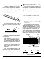
■ Installation Procedure — Tape
1. Mark the optimum position for
installation.
The pickup should be located between the
bridge pickup and bridge, ideally 20-mm from the
bridge. If the ideal 20-mm placement is not
possible, the pickup should be located as far as
possible, but no more than 20 millimeters away
from the bridge. The cable end of the pickup
should be oriented toward the sixth string (low E).
One pair of the pickup’s magnetic yokes should be
under each string. String spacing varies somewhat
on different guitars, and the pickup will function
properly as long as each string passes over part of
the corresponding yokes (not necessarily the exact
center). Check that the strings pass over the yokes,
even when bending the strings.
• Self-tapping round-head
screws (3x25mm) ...... 2
• Springs....................... 2
• Double-sided adhesive
tape ............................ 4
• Pickup cushion .......... 1
• Pickup spacers A
(1mm)......................... 5
• Pickup spacers B
(0.3mm).................... 10
• Re-usable double-sided
adhesive pads ............ 2
Bridge
Pickup
OK OK NG
String
Pickup’s magnetic yokes
■ NOTES
• Make sure the pickup does not interfere with the
operation of a tremolo arm or other guitar controls.
• If the bridge side pickup of your guitar is a hum-
bucking type, attach the divided pickup to the bridge
side pickup. (See above illustration.)
Once the pickup has been positioned correctly,
carefully mark the position on the guitar body.
Small pieces of marking tape can be used if you
don’t want to mark directly on the guitar body.
No more than
20 millimeters
(3/4")
Bridge pickup

9
2. Set the pickup height.
First make sure the truss rod and string height
are adjusted properly, then tune the strings to their
normal pitch. Adjust the height of the pickup —
using the appropriate spacer or combination of
spacers (see “NOTES” below) — so that the dis-
tance between the top of the pickup and the bottom
of each string is about 1 millimeter (0.04") when
each string is fretted at the highest note on the neck.
The pickup height can be checked by using the
supplied clearance gauge.
The distance between the pickup and the bottom
of the strings can be set less than 1 mm as long as
the strings do not touch the pickup when fretted at
the highest note on the neck.
3. Attach the pickup.
Remove the strings from the guitar. Apply the
double-sided tape to the bottom of the pickup and
remove the backing. Remove the backing from the
required pickup cushion/spacers and carefully
attach them to the bottom of the pickup. Finally,
carefully attach the pickup/spacer assembly to the
guitar at the marked position, then re-string and
tune the guitar.
Cut
Double-sided
adhesive tape
Pickup
Cushion
Spacers A, B
■ NOTES
• The re-usable double-sided adhesive pads (page 8)
can be used in place of the bottom layer of adhesive
tape (guitar side). Cut the pads to match the shape of
the pickup, as required.
4. Check the height.
Check the pickup height again, and play the
guitar in all ranges to ensure that the strings do not
come in contact with the pickup. If all is well, then
the installation is complete.
Bridge pickup
Pickup
Bridge
Installation
Cut spacers
Cut
Double-sided
adhesive tape
Guitar body
1 millimeter (0.04")
■ NOTES
• Don’t remove the backing from the pickup cushion or
spacers when initially setting up the pickup height.
Please note that the cushion/spacer backing adds
about 0.1 millimeter (0.004") to their thickness, so
take this added thickness into account when using a
number of spacers.
• To compensate for differences in height between the
first and sixth strings (e.g. if your guitar has an arched
top), use an appropriate number of one-quarter or
one-third width spacers under the lower end of the
pickup (the spacers can be cut easily with a good pair
of scissors).
1 millimeter
(0.04")
20 millimeter
(3/4")
Clearance
gauge

10
Installation
If you need to readjust the pickup height …
If the pickup height needs to be re-adjusted,
remove the strings and carefully pry the pickup
from the guitar by sliding a thin, flat object (e.g. a
small knife blade) under the sixth-string end of the
pickup — between the pickup and top spacer —
and gently lifting the pickup away from the spacer.
Readjust the height as required by adding or
removing spacers:
• To add a new spacer in order to raise the
pickup, remove any used double-sided tape
from the existing spacer, then attach the new
spacer to the top of the existing spacer after
removing its backing.
• When removing a spacer to lower the pickup,
be sure to remove both the spacer and its
backing tape.
Finally, attach fresh double-sided tape to the
bottom of the pickup, remove the backing, care-
fully attach the pickup to the uppermost spacer,
then re-string and tune the guitar.
■
Installation Procedure — Screw
Screw installation has several advantages over
tape installation: screw installation is more secure,
the height of the pickup can be more precisely
adjusted., and pickup height can be easily re-
adjusted as required without having to remove and
reattach double-sided tape.
■ NOTES
• Screw installation requires at least a 13 millimeter
(1/2”) space between the guitar top and strings.
• Adjust the pickup height using spacers (no springs) if
the distance between guitar top and strings is less
than 13 mm.
1. Mark the optimum position for
installation.
The pickup should be located between the
bridge pickup and bridge (see “NOTES” below).
The cable end of the pickup should be oriented
toward the sixth string (low E). One pair of the
pickup’s magnetic yokes should be under each
string. String spacing varies somewhat on different
guitars, and the pickup will function properly as
long as each string passes over part of the corre-
sponding yokes (not necessarily the exact center).
The double-sided tape can then be “rolled” off
the bottom of the pickup as shown in the illustra-
tion.
Bridge
Pickup
Bridge pickup
OK OK NG
String
Pickup’s magnetic yokes
No more than
20 millimeters
(3/4")

11
Installation
■ NOTES
• The pickup should be located as far as possible but
no more than 20 millimeters (3/4") from the bridge.
• Make sure the pickup does not interfere with the
operation of a tremolo arm or other guitar controls.
Once the pickup has been positioned correctly,
carefully mark the centers of the two screw holes
at either end of the pickup on the guitar body using
a fine pen or scribe.
2. Drill the screw holes.
Remove the strings from the guitar and very
carefully drill 2-millimeter (0.08", approx.) holes
at the marked locations. The holes may have to be
slightly larger in diameter if your guitar’s body is
made from a very hard wood such as maple,
cherry, or rosewood.
3. Attach the pickup.
Insert the two self-tapping round-head screws
(3x25mm) through the screw holes in the pickup,
and place the springs over the screw shafts extend-
ing below the pickup. Screw the screws in the
corresponding holes in the guitar top.
■ CAUTION!
• Be careful not to damage the pickup cable when
installing the pickup.
4. Re-string and adjust the pickup
height.
Re-string and tune the guitar, then carefully
adjust the pickup height by loosening or tightening
the pickup screws. The distance between the top of
the pickup and the bottom of each string should be
about 1 millimeter (0.04") when each string is
fretted at the highest note on the neck. The pickup
height can be checked by using the supplied
clearance gauge.

12
G
U
I
T
A
R
M
I
X
S
Y
N
T
H
U
P
D
O
W
N
V
O
L
Setup
Setup
Once installation is complete, you’re ready
to connect and check out your MIDI guitar
system (assuming you also have a G50 Guitar
MIDI Converter and appropriate tone-genera-
tor/sound hardware).
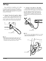
1. Connect the direct guitar cable.
Connect the 1/4" mono phone plug end of the
direct guitar cable (supplied with the G1D) to the
guitar’s output jack, and the mono mini-plug end
of the cable to the G1D direct guitar input jack.
2. Connect the G1D to the G50.
After making sure that the G50 Guitar MIDI
Converter power is OFF, plug one end of the multi-
pin cable supplied with the G50 into the G1D
multi-pin connector, and the other end into the
DIVIDED INPUT connector on the G50. The
release button on the multi-pin plug should face
outward.
■ NOTES
• Always connect the direct guitar cable, even if you
don’t intend to use the direct guitar sound. The
direct guitar cable is essential for proper grounding,
to minimize noise and prevent electric shock.
■ NOTES
• For extra security and damage prevention it is a good
idea to pass the cable between the strap and guitar
body near the body strap pin.
GUITAR
MIX
SYNTH
UP
DOWN
VOL
DIVIDED
MONO SYNTH
Multi-pin cable
Direct guitar cable
Multi-pin cable
Strap

13
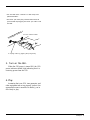
Setup
• See the G50 owner’s manual for G50 setup and
operation details.
• The multi-pin cable plug release button must be
pressed when unplugging the multi-pin cable from
the G1D.
G
U
ITAR M
ID
I
CONVERTER
DIVIDED
2. Unplug cable by gripping the puing firmly.
1. Press release button.
3. Turn on the G50.
When the G50 power is turned ON, the G1D
power indicator should light indicating that it is
receiving power from the G50.
4. Play.
Assuming that your G50, tone generator, and
other equipment are set up properly (refer to the
appropriate owner’s manuals for details), you’re
now ready to play.

14
Specifications
Specifications
■ Functions
• Volume Control (VOL)
• GUITAR/MIX/SYNTH Selector
• UP/DOWN Buttons
• Power Indicator
• Pickup (individual-string synthesizer output)
• Direct Guitar Input Jack
• Multi-pin Cable Connector
(individual-string synthesizer output + direct guitar sound)
■ Package Contents
• Pickup & Controller Unit
• Direct guitar cable (1/4" mono phone <--> mono mini-plug)
• Installing hardware parts
■ Dimensions (W x H x D)
85.1mm x 75.9mm x 28.8mm (3-1/3" x 3" x 1-1/8")
■ Weight
70 g (2.5 oz)

15
M.D.G., EMI Division © Yamaha Corporation 1996
VU83880 706POCP5.2-03C0 Printed in Japan
-
 1
1
-
 2
2
-
 3
3
-
 4
4
-
 5
5
-
 6
6
-
 7
7
-
 8
8
-
 9
9
-
 10
10
-
 11
11
-
 12
12
-
 13
13
-
 14
14
-
 15
15
-
 16
16


på andra språk
- italiano: Yamaha G1D Manuale del proprietario
- čeština: Yamaha G1D Návod k obsluze
- español: Yamaha G1D El manual del propietario
- Deutsch: Yamaha G1D Bedienungsanleitung
- polski: Yamaha G1D Instrukcja obsługi
- português: Yamaha G1D Manual do proprietário
- français: Yamaha G1D Le manuel du propriétaire
- Türkçe: Yamaha G1D El kitabı
- English: Yamaha G1D Owner's manual
- dansk: Yamaha G1D Brugervejledning
- русский: Yamaha G1D Инструкция по применению
- suomi: Yamaha G1D Omistajan opas
- Nederlands: Yamaha G1D de handleiding
- română: Yamaha G1D Manualul proprietarului