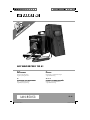
Parkside PESG 120 A1 Original Operating Instructions
- Typ
- Original Operating Instructions

IAN 85053
K O
ARC WELDER
Operation and Safety Notes
Original operating instructions
U
ELSVETS
Bruksanvisning och säkerhetsanvisningar
Original-bruksanvisning
G
ELEKTRISK SVEJSEAPPARAT
Brugs- og sikkerhedsanvisninger
Original betjeningsvejledning
F A C
ELEKTRO-SCHWEISSGERÄT
Bedienungs- und Sicherheitshinweise
Originalbetriebsanleitung
U G
ARC WELDER PESG 120 A1
Anl_1549052.indb 1Anl_1549052.indb 1 24.10.12 14:0224.10.12 14:02

- 2 -
K O
Before reading, unfold the page containing the illustrations and familiarise yourself with all functions of
the device.
U
Vik ut bildsidan och ha den till hands när du läser igenom anvisningarna och gör dig bekant med appa-
ratens / maskinens funktioner.
G
Før du læser, vend siden med billeder frem og bliv bekendt med alle apparatets funktioner.
F A C
Klappen Sie vor dem Lesen die Seite mit den Abbildungen aus und machen Sie sich anschließend mit
allen Funktionen des Gerätes vertraut.
GB/IE Operation and Safety Notes Page 5
SE Bruksanvisning och säkerhetsanvisningar Sidan 17
DK Brugs- og sikkerhedsanvisninger Side 29
DE/AT/CH Bedienungs- und Sicherheitshinweise Seite 41
Anl_1549052.indb 2Anl_1549052.indb 2 24.10.12 14:0224.10.12 14:02

- 3 -
1
2
6
4
2
1
7
3
9
8
5
3
s r
n
o
p
q
k l m m
lk
Anl_1549052.indb 3Anl_1549052.indb 3 24.10.12 14:0224.10.12 14:02

- 4 -
4 5
8 9
6 7
q
s
q
n q
n
k,l,m
1.
2.
3.
4.
p
p
p
o
r
o
s
p
Anl_1549052.indb 4Anl_1549052.indb 4 24.10.12 14:0224.10.12 14:02

GB/IE
- 5 -
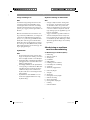
Table of contents
The reprinting or reproduction by any other means, in whole or in part, of documentation and papers
accompanying products is permitted only with the express consent of the iSC GmbH.
Subject to technical changes
1. Introduction .................................................................................................................................................. 7
2. Safety information ....................................................................................................................................... 7
3. Layout and items supplied .......................................................................................................................... 9
4. Proper use ..................................................................................................................................................10
5. Symbols and technical data.....................................................................................................................10
6. Assembling the welding screen ................................................................................................................11
7. Welding preparations ...............................................................................................................................11
8. Welding ......................................................................................................................................................11
9. Overheating guard ................................................................................................................................... 12
10. Transport .................................................................................................................................................... 12
11. Maintenance ............................................................................................................................................. 12
12. Storage ...................................................................................................................................................... 12
13. Ordering replacement parts .................................................................................................................... 12
14. Disposal and recycling ............................................................................................................................. 12
15. Circuit diagram.......................................................................................................................................... 14
16. Declaration of conformity ......................................................................................................................... 15
17. Warranty certifi cate ..................................................................................................................................16
Anl_1549052.indb 5Anl_1549052.indb 5 24.10.12 14:0224.10.12 14:02

GB/IE
- 6 -
Read and follow the operating instructions and safety information before using for the fi rst time.
Anl_1549052.indb 6Anl_1549052.indb 6 24.10.12 14:0224.10.12 14:02

GB/IE
- 7 -
1. Introduction
Congratulations on your new purchase.
You have decided in favor of a high-quality pro-
duct. The operating instructions are a part of this
product. They contain information of importance
for your safety, for the use of the product and for
its disposal. Before you use the product, acquaint
yourself with all the information concerning its
operation and safety. Use the product only as
described and only for the listed areas of applica-
tion. If you hand on the product to other people,
give them all the documentation as well.
2. Safety information
Please note
Warning!
Use this equipment only for the purpose for which
it is designed, as described in these instructions:
Manual arc welding with coated electrodes.
Handling this system incorrectly may be hazar-
dous for persons, animals and property and may
result in burning buildings, electric shocks, eye
injuries, etc. The user of this system is responsible
for his/her own safety and for the safety of others.
Read these operating instructions and follow all
the information.
•
Repairs and/or maintenance work must be
left strictly to qualified personnel.
•
Only use the welding cables supplied
(H07RN-F 3x1.0 mm
2
/ H01N2-D 1x10
mm
2
).
•
Ensure that the equipment is looked after pro-
perly.
•
To ensure that sufficient air can be drawn in
through the ventilation slits, the equipment
should not be constricted or placed next to a
wall while it is operating. Make sure that the
equipment is correctly connected to the mains
supply (see 5.). Do not subject the mains lead
to any tensile stress. Unplug the equipment
before you change its position.
•
Check the condition of the welding cables,
the electrode holder and the earth terminals;
wear on the insulation and the live parts may
result in dangerous conditions and reduce the
quality of the welding work.
•
Arc welding generates sparks, molten metal
particles and smoke, so the following is requi-
red: Remove all inflammable substances and/
or materials from the working area.
•
Ensure that there is adequate ventilation.
•
Do not weld on tanks, vessels or pipes that
have contained inflammable liquids or gases.
Avoid all direct contact with the welding cir-
cuit; the idling voltage between the electrode
holder and the earth terminal may be dange-
rous.
•
Do not store or use the equipment in wet or
damp conditions or in the rain.
•
Protect your eyes with specially designed
goggles (DIN level 9-10), which you can
attach to the supplied welding screen. Wear
gloves and dry safety clothing that are not
contaminated by any oil or grease to ensure
that your skin is not exposed to ultraviolet ra-
diation from the arc.
•
Do not use this welder to defrost pipes.
•
Make sure that the equipment is set up so it
stands firmly. If the equipment is set up on an
angled surface, it may need to be secured by
tying or blocking the wheels.
Hazard!
•
The radiation from the arc can damage your
eyes and cause burns on skin.
•
Arc welding generates sparks and droplets
of molten metal; the welded workpiece may
start to glow and will remain very hot for a
relatively long period of time. Never touch the
workpiece with bare hands.
•
Arc welding releases vapors that may be
harmful. Every electric shock is potentially
fatal.
•
Do not approach the arc within a radius of 15
m unprotected.
•
Protect yourself (and others around you)
against the possible hazardous effects of the
arc.
•
Warning: depending on the mains connection
conditions at the connection point of the wel-
ding set, other consumers connected to the
mains may suffer faults.
Anl_1549052.indb 7Anl_1549052.indb 7 24.10.12 14:0224.10.12 14:02

GB/IE
- 8 -
Warning!
If the supply mains and circuits are overloaded,
other consumers may suffer interference during
the welding work. If you have any doubts, contact
your electricity supply company.
Sources of danger during arc welding
Hazard!
Arc welding results in a number of sources of
danger. It is therefore particularly important for
the welder to comply with the following rules so
as not to place himself or others in danger and to
avoid endangering people and equipment.
•
Have all work on the mains voltage system,
for example on cables, plugs, sockets, etc.,
performed only by trained electricians. This
particularly applies to configuring intermedia-
te cables.
•
If an accident occurs, disconnect the welding
power source from the mains immediately.
•
If electric touch voltages occur, switch off the
welding set immediately and have it checked
by an expert.
•
Always check for good electrical contacts on
the welding current side.
•
Wear insulating gloves on both hands for
welding. These offer protection from electric
shocks (idling voltage in the welding circuit),
harmful radiation (heat and UV radiation) and
from glowing metal and slag spatter.
•
Wear firm, insulated footwear. Your shoes
must also be suitable to protect you in wet
conditions. Open-toed footwear is not suita-
ble since falling droplets of glowing metal will
cause burns.
•
Wear suitable clothing, do not wear synthetic
clothes.
•
Do not look into the arc with unprotected
eyes, use only a welding screen with the
proper safety glass in compliance with DIN
standards. In addition to light and heat, which
may cause dazzling and burns, the arc also
gives off UV radiation. Without proper protec-
tion, this invisible ultraviolet radiation causes
very painful conjunctivitis, which will only be
noticeable several hours later. In addition,
UV radiation will cause harmful sunburn-type
symptoms on unprotected parts of the body.
•
Personnel or assistants in the vicinity of the
arc must also be notified of the dangers and
provided with the required protection; if ne-
cessary install safety walls.
•
Ensure adequate ventilation for welding,
particularly in small rooms since the process
causes smoke and harmful gases.
•
Do not carry out any welding work on tanks
that have been used to store gases, fuels,
mineral oil or the like, even if they have been
empty for a lengthy period of time, since any
residue will result in a danger of explosion.
•
Special regulations apply in areas where the-
re is a potential risk of fire and/or explosion.
•
Welds that are exposed to large stresses and
must comply with safety requirements may
only be completed by specially trained and
approved welders. Examples of such welds
include pressure vessels, rails, trailer hitches,
etc.
•
Notes:
It must be noted that the protective con-
ductor in electrical systems or equipment may
be destroyed by the welding current in the
event of negligence, for example if the earth
terminal is placed on the welding set casing
to which the protective conductor of the elec-
trical system is connected. The welding work
is completed on a machine with a protective
conductor connection. It is therefore possible
to weld on the machine without having con-
nected the earth terminal to it. In this case the
welding current will flow from the earth ter-
minal through the protective conductor to the
machine. The high welding current may cause
the protective conductor to melt.
•
The fuses on the supply cables to the mains
sockets must comply with the relevant regulati-
ons (VDE 0100). To comply with these regula-
tions, only fuses or circuit breakers suitable for
the cross-section of the cables may be used
(for earthing contact sockets max. 13 A fuses
or 13 A circuit breakers). The use of too high
a fuse may result in the cable burning and fire
damage to the building.
Anl_1549052.indb 8Anl_1549052.indb 8 24.10.12 14:0224.10.12 14:02

GB/IE
- 9 -
Constricted and wet areas
Caution!
When working in constricted, wet or hot areas,
use insulating supports and intermediate layers
as well as slip-on gloves made of leather or other
non-conductive materials to insulate your body
against the fl oor, walls, conductive parts of the
equipment and the like.
If you use small welding transformers for wel-
ding in places with an increase electrical risk,
for example in constricted areas with conductive
walls, (tanks, pipes, etc.), in wet areas (which
make work clothes wet) and in hot areas (pers-
piration on work clothes), the output voltage of
the welding set when idling must not exceed 42
V (effective value). Therefore, the equipment may
not be used for these purposes because its output
voltage is higher than this.
Safety clothing
Caution!
•
While working, the welder must protect his
entire body from radiation and burns by wea-
ring suitable clothing and a face guard.
•
Slip-on gloves made of a suitable material
(leather) must be worn on both hands. They
must be in perfect condition.
•
Suitable aprons must be worn to protect
clothing from sparks and burns. A safety suit
and, if necessary, head protection must be
worn if required by the type of work in questi-
on, e.g. overhead welding.
•
The safety clothing used as well as all acces-
sories must comply with the directive on “per-
sonal safety equipment”.
Protection from radiation and burns
Caution!
•
Provide information about the risk to eyes at
the working site in the form of a poster with
the wording “Caution – do not look at the
flames”. Workplaces are to be screened off
wherever possible so that personnel in the
vicinity are protected. Unauthorized persons
are to be kept away from the welding work.
•
The walls in the immediate vicinity of stationa-
ry workplaces may not have a light color or a
sheen. Windows up to head height are to be
protected against radiation passing through
them or reflecting off them, for example by
coating them with a suitable paint.
3. Layout and items supplied
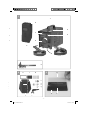
3.1 Layout (Fig. 1)
1. Carry handle
2. Welding current scale
3. ON/OFF switch
4. Earth terminal
5. Electrode holder
6. Adjustment wheel for welding current
7. Warning lamp for overheating
8. Welding screen
9. Wire brush / slag hammer
k Safety glass frame
l Welding glass
m Safety glass
n Safety glass retaining bushes
o Nuts for handle
p Screws for handle
q Safety glass retaining pins
r Handle
s Welding screen frame
3.2 Items supplied
•
Open the packaging and take out the equip-
ment with care.
•
Remove the packaging material and any
packaging and/or transportation braces (if
available).
•
Check to see if all items are supplied.
•
Inspect the equipment and accessories for
transport damage.
•
If possible, please keep the packaging until
the end of the guarantee period.
Anl_1549052.indb 9Anl_1549052.indb 9 24.10.12 14:0224.10.12 14:02

GB/IE
- 10 -
Important!
The equipment and packaging material
are not toys. Do not let children play with
plastic bags, foils or small parts. There is
a danger of swallowing or suffocating!
4. Proper use
The electric welder can be used to weld various
metals using the appropriate coated electrodes.
The equipment is to be used only for its prescribed
purpose. Any other use is deemed to be a case of
misuse. The user / operator and not the manufac-
turer will be liable for any damage or injuries of
any kind caused as a result of this.
The equipment is to be used only for its prescribed
purpose. Any other use is deemed to be a case of
misuse. The user / operator and not the manufac-
turer will be liable for any damage or injuries of
any kind caused as a result of this.
Please note that our equipment has not been de-
signed for use in commercial, trade or industrial
applications. Our warranty will be voided if the
machine is used in commercial, trade or industrial
businesses or for equivalent purposes.
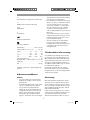
5. Symbols and technical data
EN 60974-6
European standard for arc welding sets and wel-
ding power supplies with limited on time (part 6).
Symbol for welding power supplies which are sui-
table for welding in environments with increased
electrical danger.
~ 50 Hz
Alternating current and rated frequency value
[Hz]
U
0
Rated idling voltage [V]
40A/19.6V - 80 A/21.2 V
Maximum welding current and the corresponding
standardized operating voltage [A/V]
Ø
Electrode diameter [mm]
I
2
2
Welding current [A]
tw
w
Average load time [s]
tr
r
Average reset time [s]
1 ~ 50 Hz
Line input; number of phases, the alternating cur-
rent symbol and the rated frequency value
Do not store or use the equipment in wet or damp
conditions or in the rain. Use the equipment only
indoors.
U
1
Line voltage [V]
I1max
1max
Highest rated value of the line current [A]
I
1eff
1eff 1
Effective value of the highest line current [A]
IP 21S
Protection type
H
Insulation class
Electrode holder connection
Ground terminal connection
Anl_1549052.indb 10Anl_1549052.indb 10 24.10.12 14:0224.10.12 14:02

GB/IE
- 11 -
Mains connection: .........................230 V ~ 50 Hz
Welding current (A) at cos Ê = 0.73: ...... 40 - 80
ø (mm) ..............................1,6 ...........2,0 ...........2,5
I
2
.......................................40 ............55 ............80
t
w
(s) ..................................217 ...........116 ............64
t
r
(s) ............................... 1450 ........ 1381 ........1351
Idling voltage (V): ..............................................48
Power input: .............4 kVA at 80 A cos Ê = 0.73
Fuse (A): ............................................................... 13
Weight: ....................................................... 10.6 kg
The welding times apply for an ambient tempera-
ture of 40° C.
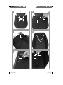
6. Assembling the welding
screen
(Fig. 3-9)
•
Place the welding glass (l) and the transparent
safety glass (m) over it in the frame for the
safety glass (k) (Fig. 3).
•
Press the safety glass retaining pins (q) into
the holes in welding screen frame (s) from the
outside. (Fig. 4)
•
Place the frame for the safety glass (k) with
the welding glass (l) and transparent safety
glass (m) from the inside into the recess in the
welding frame (s), press the safety glass retai-
ning bushes (n) onto the safety glass retaining
pins (q) until they engage to secure the frame
for the safety glass (k). The transparent safety
glass (m) must be on the outside. (Fig. 5)
•
Bend the top of the welding screen frame (s)
inwards (Fig. 6/1) and fold down the top
corners (Fig. 6/2). Now bend the outer sides
of the welding screen frame (s) inwards (Fig.
6/3) and connect them by pressing the top
corners and outer sides together. When the
retaining pins engage, you should be able to
hear 2 clear clicks on each side (Fig. 6/4).
•
When the top corners of the welding screen
are connected as shown in Figure 7, place
the screws for the handle (p) from the outside
through the three holes in the welding screen.
(Fig. 8)
•
Turn over the welding screen and place the
handle (r) over the threads on the three screws
for the handle (p). Secure the handle (r) to
the welding screen using the three nuts for the
handle (o). (Fig. 9)
7. Welding preparations
Connect the earth terminal (4) direct to the part
to be welded or to the support on which the part
is resting. Ensure that the earth terminal is in direct
contact with the part to be welded. You should
therefore avoid coated surfaces and/or insula-
ted materials. The electrode holder cable has a
special clamp (electrode holder (5)) at one end,
which is used to secure the electrode. The welding
screen (8) must be used at all times for welding. It
protects your eyes from the radiation emitted by
the arc and nevertheless enables you to watch the
welding process.
8. Welding
After you have made all the electrical connections
for the power supply and for the welding circuit,
you can proceed as follows:
Insert the unsheathed end of the electrode into the
electrode holder (5) and connect the earth termi-
nal (4) to the part you wish to weld. Ensure that a
good electric contact is made.
Switch on the welding set at the ON/OFF switch
(3) and set the welding current using the setting
wheel (6) to suit the electrode you wish to use.
Hold the welding screen in front of your face and
rub the tip of the electrode on the part you wish
to weld as if you were striking a match. This is the
best method of igniting the arc.
Check on a test part that you have the correct
electrode and current strength.
Electrode (Ø mm):...................Welding current (A)
1.6 ........................................................................40
2 ...........................................................................55
2.5 ........................................................................80
Anl_1549052.indb 11Anl_1549052.indb 11 24.10.12 14:0224.10.12 14:02

GB/IE
- 12 -
Important!
Do not dab the workpiece with the electrode since
it could be damaged, making it more diffi cult to
ignite the arc.
As soon as the arc has ignited, attempt to keep it
a distance from the workpiece equivalent to the
diameter of the electrode. This distance should be
kept as constant as possible during the welding
process. The angle of the electrode in the direction
in which you are working should be 20/30°.
Important!
Always use tongs to remove spent electrodes and
to move parts that you have just welded. Please
note that the electrode holder (5) must always
be put down so that it is insulated after you have
completed the welding work. Do not remove the
slag until the weld has cooled. If you want to con-
tinue a weld after an interruption, the slag from
your initial attempt must fi rst be removed.
9. Overheating guard
The welding set is fi tted with an overheating guard
that protects the welding transformer from over-
heating. If the overheating guard trips, the control
lamp (7) on your set will be lit. Allow the welding
set to cool for a time.
10. Transport
Before transporting the welder you must fi rst dis-
connect the power plug and remove the ground
terminal from the workpiece. Then wind up the
cable properly. Now you can carry the welder to
a different place by the carry handle (1).
11. Maintenance
Remove dust and dirt from the equipment at regu-
lar intervals. Cleaning is best carried out with a
fi ne brush or a cloth.
12. Storage
Store the equipment and accessories out of
children’s reach in a dark and dry place at above
freezing temperature. The ideal storage tempe-
rature is between 5 and 30 °C. Store the electric
tool in its original packaging.
13. Ordering replacement parts
Please quote the following data when ordering
replacement parts:
•
Type of machine
•
Article number of the machine
•
Identification number of the machine
For our latest prices and information please go to
www.isc-gmbh.info
14. Disposal and recycling
The unit is supplied in packaging to prevent its
being damaged in transit. This packaging is raw
material and can therefore be reused or can be
returned to the raw material system.
The unit and its accessories are made of various
types of material, such as metal and plastic. De-
fective components must be disposed of as spe-
cial waste. Ask your dealer or your local council.
Anl_1549052.indb 12Anl_1549052.indb 12 24.10.12 14:0224.10.12 14:02

GB/IE
- 13 -
For EU countries only
Never place any electric power tools in your
household refuse.
To comply with European Directive 2002/96/EC
concerning old electric and electronic equipment
and its implementation in national laws, old elec-
tric power tools have to be separated from other
waste and disposed of in an environment-friendly
fashion, e.g. by taking to a recycling depot.
Recycling alternative to the return request:
As an alternative to returning the equipment to the
manufacturer, the owner of the electrical equip-
ment must make sure that the equipment is proper-
ly disposed of if he no longer wants to keep the
equipment. The old equipment can be returned to
a suitable collection point that will dispose of the
equipment in accordance with the national recyc-
ling and waste disposal regulations. This does not
apply to any accessories or aids without electrical
components supplied with the old equipment.
Anl_1549052.indb 13Anl_1549052.indb 13 24.10.12 14:0224.10.12 14:02

GB/IE
- 14 -
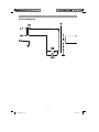
15. Circuit diagram
Anl_1549052.indb 14Anl_1549052.indb 14 24.10.12 14:0224.10.12 14:02

GB/IE
- 15 -
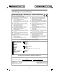
16. Declaration of conformity
Yu Feng Quing/Product-ManagementWeichselgartner/General-Manager
D erklärt folgende Konformität gemäß EU-Richtlinie und
Normen für Artikel
GB explains the following conformity according to EU directi-
ves and norms for the following product
F déclare la conformité suivante selon la directive CE et les
normes concernant l’article
I dichiara la seguente conformità secondo la direttiva UE e
le norme per l’articolo
NL verklaart de volgende overeenstemming conform EU
richtlijn en normen voor het product
E declara la siguiente conformidad a tenor de la directiva y
normas de la UE para el artículo
P declara a seguinte conformidade, de acordo com a
directiva CE e normas para o artigo
DK attesterer følgende overensstemmelse i medfør af
EU-direktiv samt standarder for artikel
S förklarar följande överensstämmelse enl. EU-direktiv och
standarder för artikeln
FIN vakuuttaa, että tuote täyttää EU-direktiivin ja standardien
vaatimukset
EE tõendab toote vastavust EL direktiivile ja standarditele
CZ vydává následující prohlášení o shodě podle směrnice EU
a norem pro výrobek
SLO potrjuje sledečo skladnost s smernico EU in standardi za
izdelek
SK vydáva nasledujúce prehlásenie o zhode podľa smernice
EÚ a noriem pre výrobok
H a cikkekhez az EU-irányvonal és Normák szerint a
következő konformitást jelenti ki
PL deklaruje zgodność wymienionego poniżej artykułu z
następującymi normami na podstawie dyrektywy WE.
BG декларира съответното съответствие съгласно
Директива на ЕС и норми за артикул
LV paskaidro šādu atbilstību ES direktīvai un standartiem
LT apibūdina šį atitikimą EU reikalavimams ir prekės normoms
RO declară următoarea conformitate conform directivei UE şi
normelor pentru articolul
GR δηλώνει την ακόλουθη συμμόρφωση σύμφωνα με την
Οδηγία ΕΚ και τα πρότυπα για το προϊόν
HR potvrđuje sljedeću usklađenost prema smjernicama EU i
normama za artikl
Izjava o sukladnosti za ovaj proizvod dostupna je na
internet stranici www.lidl.hr.
BIH potvrđuje sljedeću usklađenost prema smjernicama EU i
normama za artikl
RS potvrđuje sledeću usklađenost prema smernicama EZ i
normama za artikal
RUS следующим удостоверяется, что следующие продукты
соответствуют директивам и нормам ЕС
UKR проголошує про зазначену нижче відповідність виробу
директивам та стандартам ЄС на виріб
MK ја изјавува следната сообрзност согласно
ЕУ-директивата и нормите за артикли
TR Ürünü ile ilgili AB direktifl eri ve normları gereğince aşağıda
açıklanan uygunluğu belirtir
N erklærer følgende samsvar i henhold til EU-direktivet og
standarder for artikkel
IS Lýsir uppfyllingu EU-reglna og annarra staðla vöru
Konformitätserklärung
Elektro-Schweißgerät PESG 120 A1 (Parkside)
87/404/EC_2009/105/EC
2005/32/EC_2009/125/EC
X
2006/95/EC
2006/28/EC
X
2004/108/EC
2004/22/EC
1999/5/EC
97/23/EC
90/396/EC_2009/142/EC
89/686/EC_96/58/EC
X
2011/65/EC
2006/42/EC
Annex IV
Notifi ed Body:
Notifi ed Body No.:
Reg. No.:
2000/14/EC_2005/88/EC
Annex V
Annex VI
Noise measured: LWA = dB (A); guaranteed LWA = dB (A)
P = KW; L/Ø = cm
Notifi ed Body:
2006/28/EC
Emission No.:
Standard references: EN 60974-1; EN 60974-6; EN 60974-10
Landau/Isar, den 27.08.2012
First CE: 06 Archive-File/Record: NAPR007057
Art.-No.: 15.490.52 I.-No.: 11042 Documents registrar: Daniel Protschka
Subject to change without notice Wiesenweg 22, D-94405 Landau/Isar
Einhell Germany AG · Wiesenweg 22 · D-94405 Landau/Isar
Anl_1549052.indb 15Anl_1549052.indb 15 24.10.12 14:0224.10.12 14:02

GB/IE
17. Warranty certifi cate
Dear Customer,
All of our products undergo strict quality checks to ensure that they reach you in perfect condition. In the unlikely event
that your device develops a fault, please contact our service department at the address shown on this guarantee card.
Of course, if you would prefer to call us then we are also happy to offer our assistance under the service number prin-
ted below. Please note the following terms under which guarantee claims can be made:
1. These guarantee terms cover additional guarantee rights and do not affect your statutory warranty rights. We do
not charge you for this guarantee.
2. Our guarantee only covers problems caused by material or manufacturing defects, and it is restricted to the rec-
tifi cation of these defects or replacement of the device. Please note that our devices have not been designed for
use in commercial, trade or industrial applications. Consequently, the guarantee is invalidated if the equipment
is used in commercial, trade or industrial applications or for other equivalent activities. The following are also
excluded from our guarantee: compensation for transport damage, damage caused by failure to comply with
the installation/assembly instructions or damage caused by unprofessional installation, failure to comply with the
operating instructions (e.g. connection to the wrong mains voltage or current type), misuse or inappropriate use
(such as overloading of the device or use of non-approved tools or accessories), failure to comply with the main-
tenance and safety regulations, ingress of foreign bodies into the device (e.g. sand, stones or dust), effects of
force or external infl uences (e.g. damage caused by the device being dropped) and normal wear resulting from
proper operation of the device. This applies in particular to rechargeable batteries for which we nevertheless
issue a guarantee period of 12 months. The guarantee is rendered null and void if any attempt is made to tamper
with the device.
3. The guarantee is valid for a period of 3 years starting from the purchase date of the device. Guarantee claims
should be submitted before the end of the guarantee period within two weeks of the defect being noticed. No
guarantee claims will be accepted after the end of the guarantee period. The original guarantee period remains
applicable to the device even if repairs are carried out or parts are replaced. In such cases, the work performed
or parts fi tted will not result in an extension of the guarantee period, and no new guarantee will become active
for the work performed or parts fi tted. This also applies when an on-site service is used.
4. In order to assert your guarantee claim, please send your defective device postage-free to the address shown
below. Please enclose either the original or a copy of your sales receipt or another dated proof of purchase.
Please keep your sales receipt in a safe place, as it is your proof of purchase. It would help us if you could de-
scribe the nature of the problem in as much detail as possible. If the defect is covered by our guarantee then your
device will either be repaired immediately and returned to you, or we will send you a new device.
Of course, we are also happy offer a chargeable repair service for any defects which are not covered by the scope
of this guarantee or for units which are no longer covered. To take advantage of this service, please send the device
to our service address.
- 16 -
IAN 85053
Anl_1549052.indb 16Anl_1549052.indb 16 24.10.12 14:0324.10.12 14:03

SE
- 17 -
Innehållsförteckning
Eftertryck eller annan duplicering av dokumentation och medföljande underlag för produkterna, även
utdrag, är endast tillåtet med uttryckligt tillstånd från iSC GmbH.
Med förbehåll för tekniska ändringar.
1. Inledning ....................................................................................................................................................19
2. Säkerhetsanvisningar................................................................................................................................19
3. Beskrivning av maskinen samt leveransomfattning ............................................................................... 21
4. Ändamålsenlig användning .....................................................................................................................22
5. Symboler och tekniska data .....................................................................................................................22
6. Montera svetsskärmen .............................................................................................................................23
7. Förberedelser inför svetsning ...................................................................................................................23
8. Svetsning ....................................................................................................................................................23
9. Överhettningsskydd ..................................................................................................................................24
10. Transport ....................................................................................................................................................24
11. Underhåll ...................................................................................................................................................24
12. Förvaring ...................................................................................................................................................24
13. Reservdelsbeställning ...............................................................................................................................24
14. Skrotning och återvinning.........................................................................................................................25
15. Kopplingsschema ......................................................................................................................................26
16. Förklaring om överensstämmelse .............................................................................................................27
17. Garantibevis ..............................................................................................................................................28
Anl_1549052.indb 17Anl_1549052.indb 17 24.10.12 14:0324.10.12 14:03

SE
- 18 -
Läs igenom och beakta bruksanvisningen och säkerhetsanvisningarna före användning.
Anl_1549052.indb 18Anl_1549052.indb 18 24.10.12 14:0324.10.12 14:03

SE
- 19 -
1. Inledning
Vi gratulerar dig till ditt köp av denna nya
produkt.
Med ditt köp har du bestämt dig för en högvärdig
produkt. Bruksanvisningen är en beståndsdel till
produkten. Den innehåller viktig information för
säkerhet, användning och skrotning. Läs igenom
alla användnings- och säkerhetsanvisningar in-
nan du använder produkten. Använd produkten
endast enligt beskrivningarna samt till avsedda
användningsområden. Se till att samtliga doku-
ment medföljer om produkten ska överlåtas till en
annan person.
2. Säkerhetsanvisningar
Ska tvunget beaktas.
Varning!
Använd endast apparaten till de ändamål som
anges i denna bruksanvisning: Manuell ljusbågss-
vetsning med överdragna elektroder. Ej ändamål-
senlig användning av denna utrustning kan vara
farlig för människor, djur och materiella värden.
Det fi nns risk för tex brand i byggnader, elektris-
ka slag och ögonskador. Användaren av appara-
ten är ansvarig för sin egen och andra personers
säkerhet. Läs tvunget igenom bruksanvisningen
och beakta alla föreskrifter.
•
Reparation och/eller underhåll får endast
utföras av kvalificerade personer.
•
Det är endast tillåtet att använda de svetsled-
ningar som medföljer leveransen (H07RN-F
3x1,0mm
2
/ H01N2-D 1x10mm
2
).
•
Se till att apparaten alltid vårdas i tillräcklig
mån.
•
Under drift får apparaten inte stå i trångt
utrymme eller direkt vid en vägg eftersom
tillräcklig mängd luft måste kunna strömma
in genom öppningarna. Övertyga dig om
att apparaten har anslutits rätt till elnätet (se
punkt 5). Undvik allt slags dragbelastning på
nätkabeln. Dra ut stickkontakten innan du flyt-
tar apparaten till ett annat ställe.
•
Var uppmärksam på svetskabelns, elektrod-
hållarens samt jordklämmornas skick. Om
isoleringen eller de strömförande delarna är
slitna föreligger risk för farliga situationer,
samtidigt som svetsens kvalitet kan försämras.
•
Ljusbågssvetsning genererar gnistor, smälta
metallpartiklar och rök. Beakta därför följan-
de: Ta bort alla brännbara substanser och/
eller material från arbetsplatsen.
•
Se till att lufttillförseln alltid är tillräcklig.
•
Svetsa inte på behållare eller rör som har
innehållit brännbara vätskor eller gaser.
Undvik allt slags direktkontakt med svetsens
strömkrets. Tomgångsspänningen mellan elek-
trodhållaren och jordklämman kan vara farlig.
•
Förvara och använd inte apparaten i fuktig
eller våt omgivning eller vid regn.
•
Skydda ögonen med föreskrivna skyddsglas
(DIN grad 9-10) som du fäster på den med-
följande svetsskärmen. Använd handskar och
bär torra skyddskläder som är fria från olja
och fett för att skydda huden mot ultraviolett
strålning från ljusbågen.
•
Använd inte svetsen för att tina upp rör.
•
Kontrollera att apparaten står stabilt. Om
apparaten står på lutande underlag måste
den ev. fixeras genom att den binds fast eller
hjulen blockeras.
Fara!
•
Ljusstrålen från ljusbågen kan skada ögonen
och förorsaka brännskador på huden.
•
Vid ljusbågssvetsning uppstår gnistor och
droppar av smält metall. Det svetsade arbets-
stycket börjar glöda och förblir mycket hett
under ganska lång tid. Rör inte vid arbetssty-
cket med oskyddade händer.
•
Ångorna som frigörs vid ljusbågssvetsning
kan vara skadliga. Allt slags elektriska stötar
kan vara dödliga.
•
Närma dig inte ljusbågen inom en omkrets på
15m.
•
Skydda dig själv (och personer i närheten)
mot eventuell farlig verkan från ljusbågen.
•
Varning: Beroende på typ av nätanslutning
där svetsen har anslutits finns det risk för att
störningar uppstår i nätet som kan innebära
inskränkningar för andra användare.
Anl_1549052.indb 19Anl_1549052.indb 19 24.10.12 14:0324.10.12 14:03

SE
- 20 -
Varning!
Om elnät och strömkretsar är överbelastade
fi nns det risk för att störningar uppstår för andra
användare medan svetsen används. Kontakta din
elleverantör om du är osäker.
Riskkällor vid ljusbågssvetsning
Fara!
En rad olika riskkällor uppstår vid ljusbågssvets-
ning. Av denna anledning är det mycket viktigt att
svetsaren beaktar följande regler för att inte utsät-
ta sig själv eller andra personer för faror, eller
vålla skador på sig själv eller apparaten.
•
Arbetsuppgifter på nätspänningssidan, tex
på kablar, stickkontakt, stickuttag får endast
utföras av behörig elinstallatör. Detta gäller
särskilt för hopkoppling av mellankablar.
•
Vid olyckor ska svetsströmkällan genast åtskil-
jas från nätet.
•
Om elektriska beröringsspänningar uppstår,
koppla genast ifrån apparaten och låt en be-
hörig elinstallatör kontrollera utrustningen.
•
Se alltid till att fullgod elektrisk kontakt finns
på svetsströmsidan.
•
Bär alltid isolerande handskar på bägge hän-
derna när du svetsar. Dessa handskar skyd-
dar dig mot elektriska slag (svetsströmkretsens
tomgångsspänning), mot skadlig strålning
(värme och UV-strålning) samt mot glödande
metall och slaggstänk.
•
Bär fasta och isolerande skor. Tänk på att
skorna måste vara isolerande även om de är
våta. Vanliga skor (lågskor) är inte lämpliga
eftersom metalldroppar som faller ned kan
förorsaka brännskador.
•
Bär lämpliga kläder och använd inga syntetis-
ka plagg.
•
Titta inte in ljusbågen med oskyddade ögon.
Använd endast en svetsskärm med föreskrivet
skyddsglas enl. DIN. Ljusbågen avger inte
endast ljus- och värmestrålning, som kan
förorsaka bländning eller brännskador, utan
sänder dessutom ut UV-strålning. Om du
inte använder fullgott skydd kommer denna
osynliga ultravioletta strålning att förorsaka en
mycket smärtsam bindhinneinflammation som
dock inte märks av förrän efter några timmar.
UV-strålning på oskyddad hud leder dessu-
tom till skador som påminner om solbränna.
•
Även personer som står i närheten av ljusbå-
gen måste informeras om dessa faror och ut-
rustas med erforderlig skyddsutrustning. Bygg
in avskärmningsväggar vid behov.
•
Eftersom rök och skadliga gaser uppstår vid
svetsning måste du se till att tillräckliga mäng-
der friskluft tillförs. Detta gäller särskilt vid
svetsning i mindre rum.
•
Svetsarbeten får inte utföras vid behållare
som används för förvaring av gaser, bränsle,
mineralolja eller liknande, inte ens om de har
stått tomma under längre tid. Explosionsfara
föreligger på grund av dessa rester.
•
Särskilda föreskrifter gäller i utrymmen utsatta
för brand- och explosionsfara.
•
Svetsar som ska utsättas för höga påfrest-
ningar och tvunget måste uppfylla vissa
säkerhetsvillkor, får endast utföras av särskilt
utbildade svetsare som har genomgått prov.
Exempel: Tryckkärl, löpskenor, släpkopplin-
gar osv.
•
Instruktioner:
Tänk tvunget på att det finns risk för att skyd-
dsledaren i elektriska anläggningar eller
utrustningar förstörs av svetsströmmen om du
är oaktsam när du svetsar. Till exempel är det
möjligt att jordklämman läggs på svetsens
kåpa som är ansluten till den elektriska anläg-
gningens skyddsledare. Svetsarbetena utförs
på en maskin med skyddsledaranslutning. Det
är alltså möjligt att svetsa på maskinen utan
att jordklämman kläms fast på denna. I detta
fall leds svetsströmmen från jordklämman
via skyddsledaren till maskinen. Den höga
svetsströmmen kan leda till att skyddsledaren
smälter.
•
Tilledningarnas säkringar till nätstickutta-
gen måste uppfylla gällande föreskrifter
(VDE0100). Enligt dessa föreskrifter är det
alltså endast tillåtet att använda säkringar
resp. automater som är anpassade till led-
ningsarean (för jordade stickuttag max. 16A
säkringar eller 16A ledningsskyddsbrytare).
En säkring med för högt värde kan leda till
kabelbrand eller brandskador på byggna-
den.
Anl_1549052.indb 20Anl_1549052.indb 20 24.10.12 14:0324.10.12 14:03
Sidan laddas ...
Sidan laddas ...
Sidan laddas ...
Sidan laddas ...
Sidan laddas ...
Sidan laddas ...
Sidan laddas ...
Sidan laddas ...
Sidan laddas ...
Sidan laddas ...
Sidan laddas ...
Sidan laddas ...
Sidan laddas ...
Sidan laddas ...
Sidan laddas ...
Sidan laddas ...
Sidan laddas ...
Sidan laddas ...
Sidan laddas ...
Sidan laddas ...
Sidan laddas ...
Sidan laddas ...
Sidan laddas ...
Sidan laddas ...
Sidan laddas ...
Sidan laddas ...
Sidan laddas ...
Sidan laddas ...
Sidan laddas ...
Sidan laddas ...
Sidan laddas ...
Sidan laddas ...
Sidan laddas ...
Sidan laddas ...
-
 1
1
-
 2
2
-
 3
3
-
 4
4
-
 5
5
-
 6
6
-
 7
7
-
 8
8
-
 9
9
-
 10
10
-
 11
11
-
 12
12
-
 13
13
-
 14
14
-
 15
15
-
 16
16
-
 17
17
-
 18
18
-
 19
19
-
 20
20
-
 21
21
-
 22
22
-
 23
23
-
 24
24
-
 25
25
-
 26
26
-
 27
27
-
 28
28
-
 29
29
-
 30
30
-
 31
31
-
 32
32
-
 33
33
-
 34
34
-
 35
35
-
 36
36
-
 37
37
-
 38
38
-
 39
39
-
 40
40
-
 41
41
-
 42
42
-
 43
43
-
 44
44
-
 45
45
-
 46
46
-
 47
47
-
 48
48
-
 49
49
-
 50
50
-
 51
51
-
 52
52
-
 53
53
-
 54
54


Parkside PESG 120 A1 Original Operating Instructions
- Typ
- Original Operating Instructions
på andra språk
- Deutsch: Parkside PESG 120 A1
- English: Parkside PESG 120 A1
- dansk: Parkside PESG 120 A1
Andra dokument
-
Einhell Blue BT-EW 150 V Bruksanvisningar
-
Herkules 15.440.43 Användarmanual
-
Ferm WEM1042 Arc Welder Användarmanual
-
-
-
ESAB THE 80 Användarmanual
-
-
 Tool Up Spark 180 Användarmanual
-
-
Cebora 633 EVO 250 T Användarmanual
