
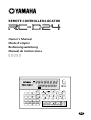
REMOTE CONTROLLER/LOCATOR
Owner’s Manual
Mode d’emploi
Bedienungsanleitung
Manual de instrucciones
PROJECT
SELECT
LOC MEM
RECALL
LOC MEM
STORE
LOCATEENTERCANCEL
0
1
4
7
2
5
8
3
6
9
PROJECT SEARCH
REMOTE CONTROLLER/LOCATOR
RTN TO
ZERO
REW FF STOP PLAY REC
ROLL
BACK
LAST REC
ABS
CAPTURE
UNIT SELECT
FSMH
ms
81UNIT 234567
SFmsM
H
SET
REPEAT
A B
REHE
B
A
AUTO
PUNCH
IN
READY
OUT
M

FCC INFORMATION (U.S.A.)
1. IMPORTANT NOTICE: DO NOT MODIFY THIS UNIT! This product, when installed as indicated in the instructions contained in this manual, meets FCC
requirements. Modifications not expressly approved by Yamaha may void your authority, granted by the FCC, to use the product.
2. IMPORTANT: When connecting this product to accessories and/or another product use only high quality shielded cables. Cable/s supplied with this product MUST
be used. Follow all installation instructions. Failure to follow instructions could void your FCC authorization to use this product in the USA.
3. NOTE: This product has been tested and found to comply with the requirements listed in FCC Regulations, Part 15 for Class “B” digital devices. Compliance with
these requirements provides a reasonable level of assurance that your use of this product in a residential environment will not result in harmful interference with
other electronic devices. This equipment generates/uses radio frequencies and, if not installed and used according to the instructions found in the users manual, may
cause interference harmful to the operation of other electronic devices. Compliance with FCC regulations does not guarantee that interference will not occur in all
installations. If this product is found to be the source of interference, which can be determined by turning the unit “OFF” and “ON”, please try to eliminate the
problem by using one of the following measures: Relocate either this product or the device that is being affected by the interference. Utilize power outlets that are on
different branch (circuit breaker or fuse) circuits or install AC line filter/s. In the case of radio or TV interference, relocate/reorient the antenna. If the antenna lead-in
is 300 ohm ribbon lead, change the lead-in to coaxial type cable. If these corrective measures do not produce satisfactory results, please contact the local retailer
authorized to distribute this type of product. If you can not locate the appropriate retailer, please contact Yamaha Corporation of America, Electronic Service
Division, 6600 Orangethorpe Ave, Buena Park, CA 90620
The above statements apply ONLY to those products distributed by Yamaha Corporation of America or its subsidiaries.

i
RC-D24—Owner’s Manual
Contents
Welcome to the RC-D24 . . . . . . . . . . . . . . 1
About this Owner’s Manual . . . . . . . . . . . 1
RC-D24 Operating Notes . . . . . . . . . . . . . 1
Touring the RC-D24 . . . . . . . . . . . . . . . . . 2
Connecting the RC-D24 . . . . . . . . . . . . . . 7
Selecting D24s in Multiple-Unit Systems . 8
Selecting Tracks for Recording . . . . . . . . . 9
Checking the Version Number . . . . . . . . . 9
Updating the System Software . . . . . . . . . 9
Specifications . . . . . . . . . . . . . . . . . . . . . . 10
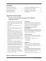
Important Information
Read the Following Before Using the RC-D24 Remote
Controller/Locator
• Do not subject the RC-D24 to extreme tem-
peratures, humidity, direct sunlight, or dust,
which could be a potential fire or electrical
shock hazard.
• Do not place heavy objects on the remote
cable.
• If the remote cable is damaged (e.g., cut or a
bare wire is exposed), ask your dealer for a
replacement.
• Do not place small metal objects on top of the
RC-D24. A metal object falling inside the
RC-D24 is a fire and electrical shock hazard.
• If you notice any abnormality—such as smoke,
odor, or noise—turn off the RC-D24 immedi-
ately and disconnect it from the D24. Confirm
that the abnormality is no longer present.
Using the RC-D24 in this condition is a poten-
tial fire and shock hazard. Consult your dealer
for repair.
• If a foreign object or water gets inside the
RC-D24, turn it off immediately and discon-
nect it from the D24. Using the RC-D24 in this
condition is a potential fire and electrical
shock hazard. Consult your dealer for repair.
• Do not attempt to modify the RC-D24. This is
a potential fire and electrical shock hazard.
• The RC-D24 operating temperature is
between 5˚C and 35˚C (41˚F and 95˚F).
• Do not use benzene, thinner, cleaning deter-
gent, or a chemical cloth to clean the RC-D24.
Use only a soft, dry cloth.
Interference
The RC-D24 uses high-frequency digital circuits
that may cause interference on radio and televi-
sion equipment located nearby. If interference is a
problem, relocate the affected equipment.
RC-D24 Exclusion of Certain
Responsibility
Manufacturer, importer, or dealer shall not be lia-
ble for any incidental damages including personal
injury or any other damages caused by improper
use or operation of the RC-D24.
Package Contents
The RC-D24 package should contain the follow-
ing items. Contact your Yamaha dealer if you are
missing an item.
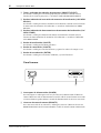
• RC-D24 Remote Controller/Locator
• Remote cable
• This manual
Trademarks
Yamaha is a trademark of Yamaha Corporation.
All other trademarks are the property of their
respective holders and are hereby acknowledged.
Copyright
No part of the RC-D24 software or this
Owner’s
Manual
may be reproduced or distributed in any
form or by any means without the prior written
authorization of Yamaha Corporation.
© 1999 Yamaha Corporation. All rights reserved.
Keep This Manual For Future Reference!

1
Welcome to the RC-D24
RC-D24—Owner’s Manual
Welcome to the RC-D24
Thank you for choosing the Yamaha RC-D24 Remote Controller/Locator. The RC-D24
is for exclusive use with the Yamaha D24 Digital Multitrack Recorder.
About this Owner’s Manual
Since most of the RC-D24 functions operate the same as on the D24, this
Owner’s Man-
ual
does not contain detailed explanations for each function. Refer to the
D24 Owner’s
Manual
for detailed information.
RC-D24 Operating Notes
The RC-D24 draws its power from the connected D24 and can be turned on or off
either before or after the D24.
If the RC-D24 is off, but the connescted D24 is on for normal poeration, there’s a pos-
sibility that noise from the remote cable may cause the D24 to malfunction. To prevent
this, disconnect the RC-D24 from the D24, or turn on the RC-D24.
In a multiple-unit system, the RC-D24 can control the entire system through Chase
mode or individual D24s. See “Selecting D24s in Multiple-Unit Systems” on page 8 for
more information.
Unlike the D24, which has two lines in the message area of the display, the RC-D24 dis-
play has just one line, which more or less corresponds to the 2nd line of the D24 display.
On the RC-D24, tracks are selected for recording using the keypad number buttons. See
“Selecting Tracks for Recording” on page 9 for more information.
The RC-D24 does not have a JOG/DATA dial, so although it can be used for auto punch
in/out recording, the Audition Take and Fix Take functions cannot be controlled
remotely. Use the D24 controls when you want to use these functions.

Touring the RC-D24
2
RC-D24—Owner’s Manual
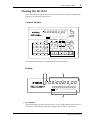
Touring the RC-D24
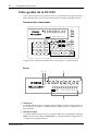
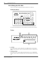
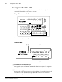
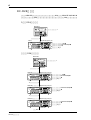
This section tours around the RC-D24’s control surface and rear panel, explaining the
purpose of each control and connector.
Control Surface
The RC-D24 control surface is explained in the following sections.
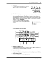
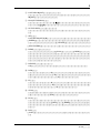
Display
A
ms indicator
This indicator lights up when the D24 counter is set to display milliseconds instead of
sub-frames. This indicator works only if supported by the D24 system software.
PROJECT
SELECT
LOC MEM
RECALL
LOC MEM
STORE
LOCATEENTERCANCEL
0
1
4
7
2
5
8
3
6
9
PROJECT SEARCH
REMOTE CONTROLLER/LOCATOR
RTN TO
ZERO
REW FF STOP PLAY REC
ROLL
BACK
LAST REC
ABS
CAPTURE
UNIT SELECT
FSMH
ms
81UNIT 234567
SFmsM
H
SET
REPEAT
A B
REHE
AUTO
PUNCH
B
A
IN
OUT
READY
00 00 00 00
REMOTE CONTROLLER/LOCATOR
FSMH
ms
81UNIT 234567
SFmsM
H
READY
00 00 00 00
0 0 0 0 0 0 0 0 0 0 0 0
21 3
4

3
Touring the RC-D24
RC-D24—Owner’s Manual
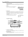
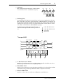
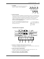
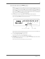
B
Quarter-note indicator
This indicator lights up when the D24 is set to display MIDI Clock information instead
of SMPTE/EBU timecode. This indicator works only if supported by the D24 system
software.
C
Counter
The counter shows the current position in hours,
minutes, seconds, and frames (00:00:00.00).
D
Message area
The message area of the display more or less corresponds to the 2nd line of the D24’s
display, and shows captured positions, locate point positions, project numbers, locate
memory numbers, take numbers, remote unit IDs, and tracks selected for recording.
Time information is displayed in hours, minutes, seconds, frames, and sub-frames
(00:00:00.00.0).
LAST REC IN, LAST REC OUT, A, and B point val-
ues are identified using the prefixes shown here.
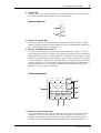
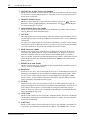
Transport Controls
A
A & B buttons & indicators
These buttons are used to set and locate the A and B points. The A and B indicators light
up when the respective A or B point is set.
B
ROLL BACK button
This button is used to roll back from the current position in steps of between 1 and 30
seconds, the default being 5 seconds.
Hour Min Sec fr sub-fr
Hour Min Sec fr
FSMH
SFmsM
H
00 00 00 00
0 0 0 0 0 0 0 0 0 0 0 0
— LAST REC IN point
— LAST REC OUT point
— A point
— B point
8
9
6
7
J K L M N
3
1
4
2
5
PROJECT SEARCH
RTN TO
ZERO
REW FF STOP PLAY REC
ROLL
BACK
LAST REC
SET
REPEAT
A B
REHE
AUTO
PUNCH
B
A
IN
OUT

Touring the RC-D24
4
RC-D24—Owner’s Manual
C
RTN TO ZERO button
This button is used to locate the zero position.
D
LAST REC IN & OUT buttons & indicators
These buttons are used to set and locate the LAST REC IN and LAST REC OUT points.
The IN and OUT indicators light up when the respective IN or OUT point is set.
E
PROJECT SEARCH buttons
These buttons are used to search for projects. Pressing the [ ] button selects the top
of the current project. Pressing the [ ] button selects the top of the next project.
F
AUTO PUNCH button & indicator
This button selects the Auto-Punch In/Out function. The AUTO PUNCH indicator
flashes when this function is on.
G
SET button
This button is used in conjunction with the LAST REC [IN], LAST REC [OUT], [A],
and [B] buttons to set the LAST REC IN, LAST REC OUT, A, and B points, respectively.
It’s also used in conjunction with the [RTN TO ZERO] button to set the relative zero
position.
The [SET] button is also used in conjunction with the [ENTER] button for the Auto
Locate Memory Store function, and in conjunction with the [LOCATE] button to set
the Keypad Timecode Input mode.
H
REHE button & indicator
This button is used to engage Rehearsal Standby mode and, when pressed together with
the [PLAY] button, punch in rehearsal. In Rehearsal mode, recording can be practiced,
with automatic playback and input monitor switching at the punch in and out points,
without actually recording anything to disk. The REHE button indicator flashes in
Rehearsal Standby mode, and lights up continuously during rehearsal.
I
REPEAT button & indicator
This button selects the A–B Repeat playback function. The REPEAT indicator lights up
when this function is on.
J
REW button
This button is used to start rewind. Press it once for rewind at 8x normal play speed, the
REW button indicator flashes. Press it again for rewind at 16x normal play speed, the
REW button indicator lights up continuously. Pressing and holding the REW button
during playback rewinds at 8x normal play speed.
K
FF button
This button is used to start fast forward. Press it once for fast forward at 8x normal play
speed, the FF button indicator flashes. Press it again for fast forward at 16x normal play
speed, the FF button indicator lights up continuously. Pressing and holding the FF but-
ton during playback fast forwards at 8x normal play speed.
L
STOP button
This button is used to stop playback, recording, rehearsal, rewind, and fast forward, and
to cancel Rehearse Standby mode. The STOP button indicator lights up when the D24
is stopped.
M
PLAY button
This button is used to start playback, punch out of recording or rehearsal, and in con-
junction with the [REC] and [REHE] buttons, punch in for recording or rehearsal,
respectively. The PLAY button indicator lights up during playback, recording, and
rehearsal.

5
Touring the RC-D24
RC-D24—Owner’s Manual
N
REC button
This button is used in conjunction with the [PLAY] button to start recording. The REC
button indicator lights up while recording.
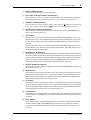
Other Buttons
O
ABS button & indicator
This button is used to set the counter mode to either Absolute (ABS), the default set-
ting, or Relative (REL). The ABS indicator lights up when Absolute (ABS) is selected.
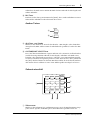
P
CAPTURE/UNIT SELECT button
This button has two functions: Capture and Unit Select. Pressed on its own, it’s used to
capture time positions while the D24 is stopped or during rewind, fast forward, play-
back, recording, or rehearsal. Captured values can be located or stored in locate mem-
ories. Pressed in conjunction with the [SET] button, it’s used to access the Unit Select
function, which is used to select individual D24s in multiple-unit systems. See “Select-
ing D24s in Multiple-Unit Systems” on page 8 for more information.
Keypad
A
Keypad buttons
The keypad is used with various functions to enter time values, parameter values,
project numbers, locate memory numbers, select tracks for recording, select individual
D24s in multiple-unit systems, and so on.
ABS
CAPTURE
UNIT SELECT
O
P
2
3
4
5
76
1
PROJECT
SELECT
LOC MEM
RECALL
LOC MEM
STORE
LOCATEENTERCANCEL
0
1
4
7
2
5
8
3
6
9

Touring the RC-D24
6
RC-D24—Owner’s Manual
B
PROJECT SELECT button & indicator
This button is used to select projects by number. The PROJECT SELECT indicator
lights up when the Project Select function is on.
C
LOC MEM RECALL button & indicator
This button is used to recall locate memories. The LOC MEM RECALL indicator lights
up when the Locate Memory Recall function is on.
D
LOC MEM STORE button & indicator
This button is used to store locate memories. The LOC MEM STORE indicator lights
up when the Locate Memory Store function is on.
E
LOCATE button
This button is used to locate positions.
F
CANCEL button
This button is used to cancel functions and reset time values to zero.
G
ENTER button
This button is used to select, confirm, and execute functions.
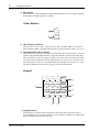
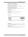
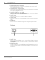
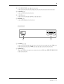
Rear Panel
A
POWER switch
This switch is used to turn on and off the RC-D24. Since the RC-D24 receives its power
via the remote cable and connected D24, the RC-D24 can only be turned on when the
D24 to which it is connected is turned on.
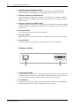
B
REMOTE connector
This 15-pin D-sub connector is used to connect the RC-D24 to the REMOTE IN/SYNC
IN connector on the D24, using the supplied remote cable.
REMOTE
POWER
ON OFF
1
2

7 Connecting the RC-D24
RC-D24—Owner’s Manual
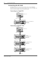
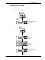
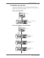
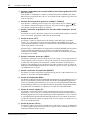
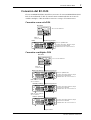
Connecting the RC-D24
The REMOTE connector on the RC-D24 should be connected to the REMOTE
IN/SYNC IN connector on the D24 using the supplied remote cable. In a multiple-unit
system, the RC-D24 should be connected to the master D24.
Connecting to a Single D24
Connecting to Multiple D24s
00 00 00 00
YAMAHA D24
OVER
READY
0
2
6
1012
1420
1830
20
42
2660
–dB
OVER
ABS H
LOCK
TIME DISPLAY
CAPTURE ABS/REL
REMAIN
VARI
SPEED
UTILITY
SETUP
PROJECT
SELECT
LOC MEM
RECALL
LOC MEM
STORE
LOCATEENTERCANCEL
0/-
1
4
7
8
R
7654321
RECORD
READY
SOLO/
SELECT
MONITOR SELECT
PEAK
HOLD
AUTO
INPUT
ALL
INPUT
FORMAT CHASE
L
2
5
8
3
6
9
UNDO/
REDO
EDIT
JOG ON
JOG/DATA SHUTTLE/
CURSOR
PROJECT SEARCH
RTN TO
ZERO
REW FF
STOP PLAY REC
ROLL
BACK
LAST REC
SET
DIGITAL MULTITRACK RECORDER
REPEAT
REHE
PHONES
LEVEL
010
ON
POWER
OFF
PHONES
BA
B
A
AUTO
PUNCH
IN
OUT
INT
24
48K
MASTER
WC
BIT
FS
TC
MSF
READY
0
2
6
12
20
30
42
60
–dB
V. TR A C K
SELECT
D24
RC-D24
WC: INT, TC: MASTER/30 fps
Chase: Off
Remote ID: 1
Unit Select: 1
REMOTE
Remote cable
REMOTE IN/SYNC IN
PROJECT
SELECT
LOC MEM
RECALL
LOC MEM
STORE
LOCATEENTERCANCEL
0
1
4
7
2
5
8
3
6
9
PROJECT SEARCH
REMOTE CONTROLLER/LOCATOR
RTN TO
ZERO
REW FF STOP PLAY REC
ROLL
BACK
LAST REC
ABS
CAPTURE
UNIT SELECT
FSMH
ms
81UNIT 234567
SFmsM
H
SET
REPEAT
A B
REHE
AUTO
PUNCH
B
A
IN
OUT
READY
00 0000 00
00 00 00 00
YAMAHA D24
OVER
READY
0
2
6
1012
1420
1830
20
42
2660
–dB
OVER
ABS H
LOCK
TIME DISPLAY
CAPTURE ABS/REL
REMAIN
VARI
SPEED
UTILITY
SETUP
PROJECT
SELECT
LOC MEM
RECALL
LOC MEM
STORE
LOCATEENTERCANCEL
0/-
1
4
7
8
R
7654321
RECORD
READY
SOLO/
SELECT
MONITOR SELECT
PEAK
HOLD
AUTO
INPUT
ALL
INPUT
FORMAT CHASE
L
2
5
8
3
6
9
UNDO/
REDO
EDIT
JOG ON
JOG/DATA SHUTTLE/
CURSOR
PROJECT SEARCH
RTN TO
ZERO
REW FF
STOP PLAY REC
ROLL
BACK
LAST REC
SET
DIGITAL MULTITRACK RECORDER
REPEAT
REHE
PHONES
LEVEL
010
ON
POWER
OFF
PHONES
BA
B
A
AUTO
PUNCH
IN
OUT
INT
24
48K
MASTER
WC
BIT
FS
TC
MSF
READY
0
2
6
12
20
30
42
60
–dB
V. TR A C K
SELECT
SYNC OUT
15-pin sync cable
REMOTE IN/SYNC IN
D24-A (master)
RC-D24
00 00 00 00
YAMAHA D24
OVER
READY
0
2
6
1012
1420
1830
20
42
2660
–dB
OVER
ABS H
LOCK
TIME DISPLAY
CAPTURE ABS/REL
REMAIN
VARI
SPEED
UTILITY
SETUP
PROJECT
SELECT
LOC MEM
RECALL
LOC MEM
STORE
LOCATEENTERCANCEL
0/-
1
4
7
8
R
7654321
RECORD
READY
SOLO/
SELECT
MONITOR SELECT
PEAK
HOLD
AUTO
INPUT
ALL
INPUT
FORMAT CHASE
L
2
5
8
3
6
9
UNDO/
REDO
EDIT
JOG ON
JOG/DATA SHUTTLE/
CURSOR
PROJECT SEARCH
RTN TO
ZERO
REW FF
STOP PLAY REC
ROLL
BACK
LAST REC
SET
DIGITAL MULTITRACK RECORDER
REPEAT
REHE
PHONES
LEVEL
010
ON
POWER
OFF
PHONES
BA
B
A
AUTO
PUNCH
IN
OUT
INT
24
48K
MASTER
WC
BIT
FS
TC
MSF
READY
0
2
6
12
20
30
42
60
–dB
V. TR A C K
SELECT
D24-B (slave)
WC: INT
TC: MASTER/30 fps
Chase: Off
Remote ID: 1
Unit Select: 1
TC: REMOTE IN/30 fps
Chase: On
Remote ID: 2
TC: REMOTE IN/30 fps
Chase: On
Remote ID: 3
Next D24
D24-C (slave)
00 00 00 00
YAMAHA D24
OVER
READY
0
2
6
1012
1420
1830
20
42
2660
–dB
OVER
ABS H
LOCK
TIME DISPLAY
CAPTURE ABS/REL
REMAIN
VARI
SPEED
UTILITY
SETUP
PROJECT
SELECT
LOC MEM
RECALL
LOC MEM
STORE
LOCATEENTERCANCEL
0/-
1
4
7
8
R
7654321
RECORD
READY
SOLO/
SELECT
MONITOR SELECT
PEAK
HOLD
AUTO
INPUT
ALL
INPUT
FORMAT CHASE
L
2
5
8
3
6
9
UNDO/
REDO
EDIT
JOG ON
JOG/DATA SHUTTLE/
CURSOR
PROJECT SEARCH
RTN TO
ZERO
REW FF
STOP PLAY REC
ROLL
BACK
LAST REC
SET
DIGITAL MULTITRACK RECORDER
REPEAT
REHE
PHONES
LEVEL
010
ON
POWER
OFF
PHONES
BA
B
A
AUTO
PUNCH
IN
OUT
INT
24
48K
MASTER
WC
BIT
FS
TC
MSF
READY
0
2
6
12
20
30
42
60
–dB
V. TR A C K
SELECT
REMOTE
Remote cable
REMOTE IN/SYNC IN
SYNC OUT
15-pin sync cable
REMOTE IN/SYNC IN
SYNC OUT
PROJECT
SELECT
LOC MEM
RECALL
LOC MEM
STORE
LOCATEENTERCANCEL
0
1
4
7
2
5
8
3
6
9
PROJECT SEARCH
REMOTE CONTROLLER/LOCATOR
RTN TO
ZERO
REW FF STOP PLAY REC
ROLL
BACK
LAST REC
ABS
CAPTURE
UNIT SELECT
FSMH
ms
81UNIT 234567
SFmsM
H
SET
REPEAT
A B
REHE
AUTO
PUNCH
B
A
IN
OUT
READY
00 0000 00

Selecting D24s in Multiple-Unit Systems 8
RC-D24—Owner’s Manual
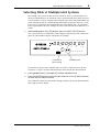
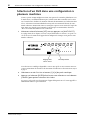
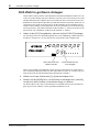
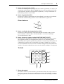
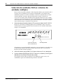
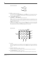
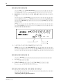
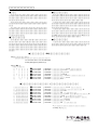
Selecting D24s in Multiple-Unit Systems
In a multiple-unit system, the RC-D24 can control the entire system through Chase
mode or individual D24s. To control the entire system through Chase mode, the Unit
Select function is set to the same ID as that assigned to the master D24. Individual D24s
can be controlled using the exclusive Remote ID number assigned to each D24. (See the
D24’s Owner’s Manual for more information on setting Remote IDs.) To control the
D24 assigned Remote ID 2, for example, the Unit Select function on the RC-D24 is set
to ID 2.
1 While holding down the [SET] button, press the [UNIT SELECT] button.
The current Unit Select setting flashes on the display, as shown below. The small circles
above the unit numbers indicate which D24s are available.
If a D24 doesn’t appear to be available, make sure that it’s connected correctly and
turned on. See page 7 for more information on connecting the RC-D24 and D24s.
2 Use keypad buttons [1] through [8] to select individual D24s.
3 Press the [ENTER] button to activate your selection, or the [CANCEL] button
to leave the Unit Select function.
The small circles above the unit numbers disappear and the previously shown informa-
tion reappears on the display.
REMOTE CONTROLLER/LOCATOR
FSMH
ms
Current Unit
Select setting
Available D24s
81UNIT 234567
SFmsM
H
READY
00 00 00 00
1

9 Selecting Tracks for Recording
RC-D24—Owner’s Manual
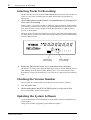
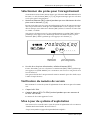
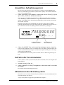
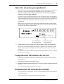
Selecting Tracks for Recording
The RC-D24 does not have dedicated RECORD READY buttons like the D24. Instead
tracks are selected for recording using the [REC] button and keypad buttons [1]
through [8].
1 While holding down the [REC] button, use keypad buttons [1] through [8] to
select tracks for recording.
When a track is selected for recording, a small circle appears above the corresponding
track number, as shown below, and the corresponding READY indicator flashes on the
D24. The Unit Select setting is displayed on the RC-D24 while the [REC] button is
pressed, as shown below.
All tracks can be selected for recording by pressing the [0] button while holding down
the [REC] button, and all tracks can deselected by pressing the [9] button while holding
down the [REC] button.
2 Release the [REC] button when you’ve selected tracks for recording.
The Unit Select setting can be changed simply by pressing the [UNIT SELECT] button
while holding down the [REC] button, allowing you to select tracks on other D24s.
Recording is started in the normal way, see the D24 Owner’s Manual for more informa-
tion.
Checking the Version Number
You can check the version number of the RC-D24 system software as follows.
1 Turn off the RC-D24.
2 While holding down the [RTN TO ZERO] button, turn on the RC-D24.
The version number appears on the display.
Updating the System Software
See the Yamaha Professional Audio Web site at the address below for information on
system updates.
<http://www.yamaha.co.jp/product/proaudio/homeenglish/>
REMOTE CONTROLLER/LOCATOR
FSMH
ms
Current Unit
Select setting
Tracks selected
for recording
81UNIT 234567
SFmsM
H
READY
00 00 00 00
1

Specifications 10
RC-D24—Owner’s Manual
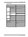
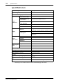
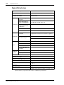
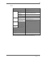
Specifications
Specifications subject to change without notice.
Repeat playback
A–B Repeat
Punch in/out
Auto, Manual, Rehearsal
Auto Punch multi-take recording
Up to 99 takes
Locate
Project Select/Search
Locate point set/search
LAST REC IN, LAST REC OUT, A, B
Locate memory store/recall
99
Return to zero
Roll back
Display
Counter
7-segment LED x 8
Time display: Hours, minutes, seconds, frames
Message area
7-segment LED x 12
Time display: Hours, minutes, seconds, frames,
sub-frames
Others
ABS/REL
CAPTURE
POWER SW
15-pin D-sub connector
Mounting
screws
Speaker bolts
M5 nut x 2
Mic stand
W3/8
Supply voltage
12 V DC
Power consumption
10 W
Dimensions (W
×
H
×
D)
214 × 50 × 138 mm (8.4 x 2 x 5.4 inches)
Weight
1 kg (2.2 lbs)
Free-air operating temperature range
0 to 40˚ C (32˚ F to 104˚ F)
Relative humidity
10–95%
Accessories
15-pin D-Sub remote cable (5 m)

Mode d’emploi
FRANÇAIS
Remote Controller/Locator

i
RC-D24—Mode d’emploil
Sommaire
Bienvenue sur la RC-D24! .......................... 1
A propos du présent Mode d’emploi ......... 1
Remarques liées à l’utilisation
de la RC-D24 ............................................... 1
Visite guidée de la RC-D24 ......................... 2
Connecter la RC-D24 .................................. 7
Sélection d’un D24 dans une
configuration à plusieurs machines ........... 8
Sélectionner des pistes pour l’enregistrement .... 9
Vérification du numéro de version ................ 9
Mise à jour du système d’exploitation ............ 9
Fiche technique ......................................... 10
Informations importantes
Veuillez lire ce qui suit avant d’utiliser la commande à distance/unité
Locator RC-D24
• Ne placez pas la RC-D24 à un endroit soumis à
des températures excessives (froides ou chau-
des), à de l’humidité ou en plein soleil. Cela
pourrait déclencher un incendie ou provoquer
une électrocution.
• Ne placez pas d’objets lourds sur le câble de la
commande à distance.
• Si le câble de la commande à distance est endom-
magé (cisaillé ou à nu), demandez un nouveau
câble à votre revendeur.
• Ne placez pas de petits objets métalliques sur la
RC-D24. Des objets tombant à l’intérieur du boî-
tier pourraient causer une électrocution voire un
incendie.
• Si vous remarquez toute anomalie — comme de
la fumée, une odeur ou un bruit suspect —, met-
tez immédiatement la RC-D24 hors tension et
débranchez-la du D24. Assurez-vous que tout est
en ordre. L’utilisation de la RC-D24 dans ces
conditions pourrait créer un risque d’incendie
ou d’électrocution. Si des réparations sont néces-
saires, contactez votre revendeur.
• Si un objet ou de l’eau a pénétré dans la RC-D24,
mettez-la immédiatement hors tension et décon-
nectez-la du D24. L’utilisation de la RC-D24
dans ces conditions pourrait créer un risque
d’incendie ou d’électrocution. Si des réparations
sont nécessaires, contactez votre revendeur.
• N’essayez pas de modifier la RC-D24. Cela pour-
rait causer une électrocution voire un incendie.
• La température de fonctionnement de la RC-D24
est comprise entre 5˚C à 35˚C (41˚F à 95˚F).
• N’utilisez pas de benzène, de diluant, de déter-
gent ou de tissu imprégné de produit chimique
pour nettoyer la RC-D24. Servez-vous unique-
ment d’un chiffon sec et doux.
Interférences
La RC-D24 se sert de circuits numériques à hautes
fréquences qui risquent d’interférer avec des radios
ou télévisions placées trop près de lui. Eloignez les
appareils s’il y a des interférences.
Exclusion de certains dommages liés à
l’emploi de la RC-D24
Ni le fabricant, ni le distributeur ou le revendeur ne
peuvent être tenus responsables pour des domma-
ges corporels ou matériels résultant d’une manipu-
lation abusive de cet appareil.
Contenu de l’emballage
L’emballage de la RC-D24 doit contenir les objets
suivants. Assurez-vous qu’il n’en manque aucun. Si
un ou plusieurs éléments manquaient, contactez
votre revendeur Yamaha.
• La commande à distance/unité Locator RC-D24
• Le câble de commande à distance
•Ce
Mode d’emploi
Marques déposées
Yamaha est une marque commerciale de Yamaha
Corporation.
Toutes les marques commerciales sont
la propriété de leurs détenteurs respectifs
et recon-
nues telles par la présente.
Copyright
Il est interdit de reproduire ou de distribuer sous
quelque forme que ce soit, en tout ou en partie, le
logiciel de la RC-D24 ou le Mode d’emploi
sans
l’autorisation écrite préalable de Yamaha Corpora-
tion.
© 1999 Yamaha Corporation. Tous droits réservés.
Veuillez conserver ce manuel pour toute référence ultérieure!

Bienvenue sur la RC-D24!
1
RC-D24—Mode d’emploi
Bienvenue sur la RC-D24!
Nous vous remercions pour avoir porté votre choix sur la commande à distance/unité
Locator RC-D24. La RC-D24 est destinée pour être employée exclusivement avec
l’enregistreur numérique multipiste D24 de Yamaha.
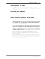
A propos du présent Mode d’emploi
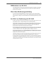
Comme la plupart des fonctions de la RC-D24 sont identiques à celles du D24, ce
Mode
d’emploi
ne s’attardera pas à chacune de ces fonctions. Pour des détails, reportez-vous
au Mode d’emploi du D24.
Remarques liées à l’utilisation de la RC-D24
La RC-D24 est alimentée par le D24 connecté et peut donc être mise sous tension et
hors tension soit avant ou après le D24.
Si la RC-D24 est éteinte alors que vous utilisez le D24, il peut arriver que le câble de la
commande à distance transmette du bruit qui provoque des dysfonctionnements du
D24. Pour éviter ce problème, déconnectez le câble ou allumez la RC-D24.
Si vous utilisez plusieurs D24, vous pourrez contrôler via la RC-D24 tous les D24 à la
fois (avec le mode Chase) ou des D24 individuels. Voyez “Sélection d’un D24 dans une
configuration à plusieurs machines” à la page 8 pour en savoir plus.
Contrairement au D24, dont l’écran comporte deux lignes de zone de message, l’écran
de la RC-D24 comporte une ligne unique (correspondant grosso modo à la seconde
ligne de l’écran du D24).
Sur la RC-D24, vous sélectionnez les pistes pour l’enregistrement via les boutons du
pavé numérique. Voyez “Sélectionner des pistes pour l’enregistrement” à la page 9 pour
en savoir plus.
La RC-D24 ne comporte pas de molette JOG/DATA; aussi, bien que vous puissiez effec-
tuer des enregistrements avec fonction Auto Punch In/Out, vous ne pouvez comman-
der à distance les fonctions Audition Take et Fix Take. Utilisez donc ces fonctions via les
commandes du D24.

2
Visite guidée de la RC-D24
RC-D24—Mode d’emploi
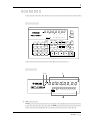
Visite guidée de la RC-D24
Cette section vous présente le panneau avant et ses commandes ainsi que le panneau
arrière de la RC-D24, en vous décrivant la fonction de chaque commande et borne.
Panneau des commandes
Le panneau des commandes de la RC-D24 est décrit dans les sections suivantes.
Ecran
A
Témoin ms
Ce témoin s’allume lorsque le compteur du D24 affiche le temps en millisecondes au
lieu de fractions de frame. Ce témoin fonctionne uniquement s’il est supporté par le
logiciel du D24.
B
Témoin de noire
Ce témoin s’allume lorsque le D24 est réglé pour afficher des informations d’horloge
MIDI au lieu du code temporel SMPTE/EBU. Ce témoin fonctionne uniquement s’il
est supporté par le logiciel du D24.
PROJECT
SELECT
LOC MEM
RECALL
LOC MEM
STORE
LOCATEENTERCANCEL
0
1
4
7
2
5
8
3
6
9
PROJECT SEARCH
REMOTE CONTROLLER/LOCATOR
RTN TO
ZERO
REW FF STOP PLAY REC
ROLL
BACK
LAST REC
ABS
CAPTURE
UNIT SELECT
FSMH
ms
81UNIT 234567
SFmsM
H
SET
REPEAT
A B
REHE
AUTO
PUNCH
B
A
IN
OUT
READY
00 00 00 00
REMOTE CONTROLLER/LOCATOR
FSMH
ms
81UNIT 234567
SFmsM
H
READY
00 00 00 00
0 0 0 0 0 0 0 0 0 0 0 0
21 3
4

Visite guidée de la RC-D24
3
RC-D24—Mode d’emploi
C
Compteur
Le compteur affiche la position actuelle en heures,
minutes, secondes et frames (00:00:00.00).
D
Zone de message
La zone de message de l’écran correspond plus ou moins à la deuxième ligne sur l’écran
du D24 et affiche les valeurs saisies, les positions de localisation directe, les numéros de
projet, les numéros de mémoire de localisation, les numéros de prise, l’identité des
appareils connectés ainsi que les pistes sélectionnées pour l’enregistrement. Les infor-
mations temporelles sont affichées en heures, minutes, secondes, frames et fractions
(dixièmes) de frame (00:00:00.00.0).
Les valeurs des points LAST REC IN, LAST REC
OUT, A et B sont identifiées via les préfixes affichés
ci-contre.
Commandes de transport
A
Boutons et témoins A & B
Ces boutons permettent de régler et de localiser les points A et B. Les témoins A et B
s’allument lorsque le point correspondant est déterminé.
B
Bouton ROLL BACK
Ce bouton vous permet de retourner en arrière à partir de la position actuelle par pas
compris entre 1 et 30 secondes. Un pas de 5 secondes est attribué par défaut à ce bouton.
C
Bouton RTN TO ZERO
Ce bouton vous permet de localiser la position zéro.
HeuresMin Sec Fr Sub-Fr
Heures Min Sec Fr
FSMH
SFmsM
H
00 00 00 00
0 0 0 0 0 0 0 0 0 0 0 0
— Point LAST REC IN
— Point LAST REC OUT
— Point A
— Point B
8
9
6
7
J K L M N
3
1
4
2
5
PROJECT SEARCH
RTN TO
ZERO
REW FF STOP PLAY REC
ROLL
BACK
LAST REC
SET
REPEAT
A B
REHE
AUTO
PUNCH
B
A
IN
OUT

4
Visite guidée de la RC-D24
RC-D24—Mode d’emploi
D
Boutons et témoins LAST REC IN & OUT
Ces boutons permettent de régler et de localiser les points LAST REC IN et LAST REC
OUT. Les témoins IN et OUT s’allument lorsque le point correspondant est déterminé.
E
Boutons PROJECT SEARCH
Ces boutons permettent de rechercher des projets. Une pression sur le bouton [ ]
vous amène au début du projet actuel tandis qu’une pression sur le bouton [ ] vous
amène au début du projet suivant.
F
Bouton et témoin AUTO PUNCH
Ce bouton sélectionne la fonction Auto-Punch In/Out. Le témoin AUTO PUNCH cli-
gnote lorsque la fonction est activée.
G
Bouton SET
Utilisez ce bouton avec les boutons LAST REC [IN], LAST REC [OUT], [A] et [B] pour
fixer respectivement les points LAST REC IN, LAST REC OUT, A et B.
Le bouton [SET] peut aussi être utilisé avec [ENTER] et donne alors accès à la fonction
d’incrémentation automatique des mémoires Locate. Si vous l’utilisez avec le bouton
[LOCATE], vous pouvez modifier le mode d’affichage du compteur.
H
Bouton & témoin REHE
Ce bouton permet de passer en mode d’attente de simulation et, lorsque vous l’action-
nez en même temps que le bouton [PLAY], en mode de simulation d’enregistrement
Punch In. Le mode de simulation (Rehearsal) permet de vous entraîner à réenregistrer
un passage avec reproduction et changement automatique d’entrée pour l’écoute aux
points Punch In/Out sans enregistrer quoi que ce soit sur disque. Le témoin REHE du
bouton clignote pour indiquer le mode d’attente de simulation et reste allumé en mode
de simulation.
I
Bouton & témoin REPEAT
Ce bouton active la fonction de reproduction répétée d’un passage compris entre A et
B. Le témoin REPEAT s’allume lorsque la fonction de répétition est activée.
J
Bouton REW
Ce bouton permet de rebobiner. Appuyez une fois dessus pour un rebobinage 8x. Une
nouvelle pression sur ce bouton permet de rebobiner à 16x fois la vitesse de reproduc-
tion (le témoin cesse alors de clignoter et reste allumé). Si vous maintenez le bouton
REW enfoncé pendant la reproduction, vous reculez à 8x la vitesse de lecture normale.
K
Bouton FF
Ce bouton permet d’avancer rapidement. Appuyez une fois dessus pour une avance 8x
la vitesse normale. Le témoin du bouton FF clignote alors. Une nouvelle pression sur ce
bouton permet d’avancer à 16x fois la vitesse de reproduction (le témoin cesse alors de
clignoter et reste allumé). Si vous maintenez le bouton FF enfoncé pendant la reproduc-
tion, vous avancez à 8x la vitesse de lecture normale.
L
Bouton STOP
Ce bouton permet d’arrêter la reproduction, l’enregistrement, la simulation, le rebobi-
nage et l’avance rapide ainsi que d’annuler le mode de simulation. Le témoin STOP du
bouton s’allume lorsque le D24 est arrêté.
M
Bouton PLAY
Ce bouton permet de lancer la reproduction, de quitter l’enregistrement ou la simula-
tion Punch In/Out et, en conjonction avec les boutons [REC] ou [REHE], de lancer
l’enregistrement ou la simulation Punch In/Out. Le témoin du bouton PLAY s’allume
durant la reproduction, l’enregistrement et la simulation.

Visite guidée de la RC-D24
5
RC-D24—Mode d’emploi
N
Bouton REC
Utilisé de concert avec le bouton [PLAY], ce bouton permet de lancer l’enregistrement.
Le témoin du bouton REC s’allume durant l’enregistrement.
Autres boutons
O
Bouton et témoin ABS
Ce bouton permet de déterminer le mode de fonctionnement du compteur: Absolu
(ABS), le réglage par défaut, ou Relatif (REL). Le témoin du bouton ABS s’allume lors-
que le mode Absolu (ABS) est sélectionné.
P
Bouton CAPTURE/UNIT SELECT
Ce bouton a deux fonctions: de saisie des positions temporelles (Capture) et de sélec-
tion d’unité D24 (Unit Select). Appuyer sur ce bouton seul permet de saisir les positions
temporelles quand le D24 est à l’arrêt ou durant le rebobinage, l’avance rapide, la repro-
duction, l’enregistrement ou la simulation. Les valeurs saisies peuvent alors être locali-
sées ou sauvegardées. Actionné avec le bouton [SET], ce bouton vous permet d’activer
la fonction Unit Select et de sélectionner un D24 individuel dans une configuration à
plusieurs machines. Voyez “Sélection d’un D24 dans une configuration à plusieurs
machines” à la page 8 pour en savoir plus.
Pavé numérique
A
Boutons du pavé numérique
Le pavé numérique est utilisé avec de nombreuses fonctions pour entrer des valeurs
temporelles, des valeurs de paramètres, des numéros de projet, des numéros de
mémoire de localisation, pour sélectionner des pistes pour l’enregistrement, pour
sélectionner des D24 individuels dans une configuration à plusieurs machines, etc.
ABS
CAPTURE
UNIT SELECT
O
P
2
3
4
5
76
1
PROJECT
SELECT
LOC MEM
RECALL
LOC MEM
STORE
LOCATEENTERCANCEL
0
1
4
7
2
5
8
3
6
9
Sidan laddas ...
Sidan laddas ...
Sidan laddas ...
Sidan laddas ...
Sidan laddas ...
Sidan laddas ...
Sidan laddas ...
Sidan laddas ...
Sidan laddas ...
Sidan laddas ...
Sidan laddas ...
Sidan laddas ...
Sidan laddas ...
Sidan laddas ...
Sidan laddas ...
Sidan laddas ...
Sidan laddas ...
Sidan laddas ...
Sidan laddas ...
Sidan laddas ...
Sidan laddas ...
Sidan laddas ...
Sidan laddas ...
Sidan laddas ...
Sidan laddas ...
Sidan laddas ...
Sidan laddas ...
Sidan laddas ...
Sidan laddas ...
Sidan laddas ...
Sidan laddas ...
Sidan laddas ...
Sidan laddas ...
Sidan laddas ...
Sidan laddas ...
Sidan laddas ...
Sidan laddas ...
Sidan laddas ...
Sidan laddas ...
Sidan laddas ...
Sidan laddas ...
Sidan laddas ...
-
 1
1
-
 2
2
-
 3
3
-
 4
4
-
 5
5
-
 6
6
-
 7
7
-
 8
8
-
 9
9
-
 10
10
-
 11
11
-
 12
12
-
 13
13
-
 14
14
-
 15
15
-
 16
16
-
 17
17
-
 18
18
-
 19
19
-
 20
20
-
 21
21
-
 22
22
-
 23
23
-
 24
24
-
 25
25
-
 26
26
-
 27
27
-
 28
28
-
 29
29
-
 30
30
-
 31
31
-
 32
32
-
 33
33
-
 34
34
-
 35
35
-
 36
36
-
 37
37
-
 38
38
-
 39
39
-
 40
40
-
 41
41
-
 42
42
-
 43
43
-
 44
44
-
 45
45
-
 46
46
-
 47
47
-
 48
48
-
 49
49
-
 50
50
-
 51
51
-
 52
52
-
 53
53
-
 54
54
-
 55
55
-
 56
56
-
 57
57
-
 58
58
-
 59
59
-
 60
60
-
 61
61
-
 62
62


på andra språk
- italiano: Yamaha RC-D24 Manuale del proprietario
- čeština: Yamaha RC-D24 Návod k obsluze
- español: Yamaha RC-D24 El manual del propietario
- Deutsch: Yamaha RC-D24 Bedienungsanleitung
- polski: Yamaha RC-D24 Instrukcja obsługi
- português: Yamaha RC-D24 Manual do proprietário
- français: Yamaha RC-D24 Le manuel du propriétaire
- 日本語: Yamaha RC-D24 取扱説明書
- Türkçe: Yamaha RC-D24 El kitabı
- English: Yamaha RC-D24 Owner's manual
- русский: Yamaha RC-D24 Инструкция по применению
- Nederlands: Yamaha RC-D24 de handleiding
- română: Yamaha RC-D24 Manualul proprietarului