


3
EMX7 Owner’s Manual
The above warning is located on the rear of the unit.
L’avertissement ci-dessus est situé sur l’arrière de l’unité.
Explanation of Graphical Symbols
Explication des symboles
The lightning flash with arrowhead symbol within an equilateral triangle is intended to alert
the user to the presence of uninsulated “dangerous voltage” within the product’s enclosure that
may be of sufficient magnitude to constitute a risk of electric shock to persons.
L’éclair avec une flèche à l’intérieur d’un triangle équilatéral est destiné à attirer l’attention de
l’utilisateur sur la présence d’une « tension dangereuse » non isolée à l’intérieur de l’appareil,
pouvant être suffisamment élevée pour constituer un risque d’électrocution.
The exclamation point within an equilateral triangle is intended to alert the user to the pres-
ence of important operating and maintenance (servicing) instructions in the literature accom-
panying the product.
Le point d’exclamation à l’intérieur d’un triangle équilatéral est destiné à attirer l’attention de
l’utilisateur sur la présence d’instructions importantes sur l’emploi ou la maintenance (réparat-
ion) de l’appareil dans la documentation fournie.
IMPORTANT SAFETY INSTRUCTIONS
1 Read these instructions.
2 Keep these instructions.
3 Heed all warnings.
4 Follow all instructions.
5 Do not use this apparatus near water.
6 Clean only with dry cloth.
7 Do not block any ventilation openings. Install in accordance with the manufacturer’s instructions.
8 Do not install near any heat sources such as radiators, heat registers, stoves, or other apparatus (includ-
ing amplifiers) that produce heat.
9 Do not defeat the safety purpose of the polarized or grounding-type plug. A polarized plug has two blades
with one wider than the other. A grounding type plug has two blades and a third grounding prong. The
wide blade or the third prong are provided for your safety. If the provided plug does not fit into your outlet,
consult an electrician for replacement of the obsolete outlet.
10 Protect the power cord from being walked on or pinched particularly at plugs, convenience receptacles,
and the point where they exit from the apparatus.
11 Only use attachments/accessories specified by the manufacturer.
12 Use only with the cart, stand, tripod, bracket, or table specified by the manufacturer,
or sold with the apparatus. When a cart is used, use caution when moving the cart/
apparatus combination to avoid injury from tip-over.
13 Unplug this apparatus during lightning storms or when unused for long periods of
time.
14 Refer all servicing to qualified service personnel. Servicing is required when the
apparatus has been damaged in any way, such as power-supply cord or plug is dam-
aged, liquid has been spilled or objects have fallen into the apparatus, the apparatus has been exposed to
rain or moisture, does not operate normally, or has been dropped.
(UL60065_03)
PRÉCAUTIONS CONCERNANT LA SÉCURITÉ
1 Lire ces instructions.
2 Conserver ces instructions.
3 Tenir compte de tous les avertissements.
4 Suivre toutes les instructions.
5 Ne pas utiliser ce produit à proximité d’eau.
6 Nettoyer uniquement avec un chiffon propre et sec.
7 Ne pas bloquer les orifices de ventilation. Installer l’appareil conformément aux instructions du fabricant.
8 Ne pas installer l’appareil à proximité d’une source de chaleur comme un radiateur, une bouche de cha-
leur, un poêle ou tout autre appareil (y compris un amplificateur) produisant de la chaleur.
9 Ne pas modifier le système de sécurité de la fiche polarisée ou de la fiche de terre. Une fiche polarisée dis-
pose de deux broches dont une est plus large que l’autre. Une fiche de terre dispose de deux broches et
d’une troisième pour le raccordement à la terre. Cette broche plus large ou cette troisième broche est des-
tinée à assurer la sécurité de l’utilisateur. Si la fiche équipant l’appareil n’est pas compatible avec les pri-
ses de courant disponibles, faire remplacer les prises par un électricien.
10 Acheminer les cordons d’alimentation de sorte qu’ils ne soient pas piétinés ni coincés, en faisant tout
spécialement attention aux fiches, prises de courant et au point de sortie de l’appareil.
11 Utiliser exclusivement les fixations et accessoires spécifiés par le fabricant.
12 Utiliser exclusivement le chariot, le stand, le trépied, le support ou la table recom-
mandés par le fabricant ou vendus avec cet appareil. Si l’appareil est posé sur un
chariot, déplacer le chariot avec précaution pour éviter tout risque de chute et de
blessure.
13 Débrancher l’appareil en cas d’orage ou lorsqu’il doit rester hors service pendant
une période prolongée.
14 Confier toute réparation à un personnel qualifié. Faire réparer l’appareil s’il a subi
tout dommage, par exemple si la fiche ou le cordon d’alimentation est endommagé, si du liquide a coulé
ou des objets sont tombés à l’intérieur de l’appareil, si l’appareil a été exposé à la pluie ou à de l’humidité,
si l’appareil ne fonctionne pas normalement ou est tombé.
(UL60065_03)
WARNING
TO REDUCE THE RISK OF FIRE OR ELECTRIC SHOCK, DO NOT EXPOSE THIS APPARATUS TO RAIN OR
MOISTURE.
AVERTISSEMENT
POUR RÉDUIRE LES RISQUES D’INCENDIE OU DE DÉCHARGE ÉLECTRIQUE, N’EXPOSEZ PAS CET
APPAREIL À LA PLUIE OU À L’HUMIDITÉ.

4
EMX7 Owner’s Manual
1. IMPORTANT NOTICE: DO NOT MODIFY THIS
UNIT!
This product, when installed as indicated in the instruc-
tions contained in this manual, meets FCC require-
ments. Modifications not expressly approved by Yamaha
may void your authority, granted by the FCC, to use the
product.
2. IMPORTANT: When connecting this product to acces-
sories and/or another product use only high quality
shielded cables. Cable/s supplied with this product
MUST be used. Follow all installation instructions. Fail-
ure to follow instructions could void your FCC authoriza-
tion to use this product in the USA.
3. NOTE: This product has been tested and found to com-
ply with the requirements listed in FCC Regulations,
Part 15 for Class “B” digital devices. Compliance with
these requirements provides a reasonable level of
assurance that your use of this product in a residential
environment will not result in harmful interference with
other electronic devices. This equipment generates/
uses radio frequencies and, if not installed and used
according to the instructions found in the users manual,
may cause interference harmful to the operation of other
electronic devices. Compliance with FCC regulations
does not guarantee that interference will not occur in all
installations. If this product is found to be the source of
interference, which can be determined by turning the
unit “OFF” and “ON”, please try to eliminate the problem
by using one of the following measures:
Relocate either this product or the device that is being
affected by the interference.
Utilize power outlets that are on different branch (circuit
breaker or fuse) circuits or install AC line filter/s.
In the case of radio or TV interference, relocate/reorient
the antenna. If the antenna lead-in is 300 ohm ribbon
lead, change the lead-in to co-axial type cable.
If these corrective measures do not produce satisfactory
results, please contact the local retailer authorized to
distribute this type of product. If you can not locate the
appropriate retailer, please contact Yamaha Corporation
of America, Electronic Service Division, 6600 Orangeth-
orpe Ave, Buena Park, CA90620
The above statements apply ONLY to those products
distributed by Yamaha Corporation of America or its
subsidiaries.
* This applies only to products distributed by YAMAHA CORPORATION OF AMERICA. (class B)
FCC INFORMATION (U.S.A.)
The model number, serial number, power requirements, etc., may be
found on or near the name plate, which is at the rear of the unit. You
should note this serial number in the space provided below and retain
this manual as a permanent record of your purchase to aid identifica-
tion in the event of theft.
Model No.
Serial No.
(rear_en_01)
In Finland: Laite on liitettävä suojamaadoituskoskettimilla varustettuun
pistorasiaan.
In Norway: Apparatet må tilkoples jordet stikkontakt.
In Sweden:Apparaten skall anslutas till jordat uttag.
(class I hokuo)
(weee_eu_en_01)
Information for Users on Collection and Disposal of Old Equipment
This symbol on the products, packaging, and/or accompanying documents means that used electrical and
electronic products should not be mixed with general household waste.
For proper treatment, recovery and recycling of old products, please take them to applicable collection
points, in accordance with your national legislation and the Directives 2002/96/EC.
By disposing of these products correctly, you will help to save valuable resources and prevent any potential
negative effects on human health and the environment which could otherwise arise from inappropriate
waste handling.
For more information about collection and recycling of old products, please contact your local municipality,
your waste disposal service or the point of sale where you purchased the items.
[For business users in the European Union]
If you wish to discard electrical and electronic equipment, please contact your dealer or supplier for further
information.
[Information on Disposal in other Countries outside the European Union]
This symbol is only valid in the European Union. If you wish to discard these items, please contact your
local authorities or dealer and ask for the correct method of disposal.

5
EMX7 Owner’s Manual
PRECAUTIONS
PLEASE READ CAREFULLY
BEFORE PROCEEDING
Please keep this manual in a safe place for
future reference.
WARNING
Always follow the basic precautions listed below to
avoid the possibility of serious injury or even death
from electrical shock, short-circuiting, damages, fire
or other hazards. These precautions include, but are
not limited to, the following:
Power supply/power cord
• Do not place the power cord near heat sources such as
heaters or radiators, and do not excessively bend or
otherwise damage the cord, place heavy objects on it, or
place it in a position where anyone could walk on, trip
over, or roll anything over it.
• Only use the voltage specified as correct for the device.
The required voltage is printed on the name plate of the
device.
• Use only the supplied power cord/plug.
If you intend to use the device in an area other than in the
one you purchased, the included power cord may not be
compatible. Please check with your Yamaha dealer.
• Check the electric plug and each jack periodically, and
remove any dirt or dust which may have accumulated.
Failure to do so may cause electrical shock, short-
circuiting or fire.
• When setting up the device, make sure that the AC outlet
you are using is easily accessible. If some trouble or
malfunction occurs, immediately turn off the power switch
and disconnect the plug from the outlet. Even when the
power switch is turned off, as long as the power cord is not
unplugged from the wall AC outlet, the device will not be
disconnected from the power source.
• Remove the electric plug from the outlet when the device
is not to be used for extended periods of time, or during
electrical storms.
• Be sure to connect to an appropriate outlet with a
protective grounding connection.
Do not open
• This device contains no user-serviceable parts. Do not
open the device or attempt to disassemble the internal
parts or modify them in any way. If it should appear to be
malfunctioning, discontinue use immediately and have it
inspected by qualified Yamaha service personnel.
Water warning
• Do not expose the device to rain, use it near water or in
damp or wet conditions, or place on it any containers
(such as vases, bottles or glasses) containing liquids
which might spill into any openings. If any liquid such as
water seeps into the device, turn off the power
immediately and unplug the power cord from the AC
outlet. Then have the device inspected by qualified
Yamaha service personnel.
• Never insert or remove an electric plug with wet hands.
Hearing loss
• Avoid setting all equalizer and level controls to their
maximum. Depending on the condition of the connected
devices, doing so may result in feedback that can cause
hearing loss and damage the speakers.
• Do not use speakers for a long period of time at a high or
uncomfortable volume level, since this can cause
permanent hearing loss. If you experience any hearing
loss or ringing in the ears, consult a physician.
• When turning on the AC power in your audio system,
always turn on the device LAST, to avoid hearing loss and
speaker damage. When turning the power off, the device
should be turned off FIRST for the same reason.
Fire warning
• Do not place any burning items or open flames near the
device, since they may cause a fire.
If you notice any abnormality
• If any of the following problems occur, immediately turn off
the power switch and disconnect the electric plug from the
outlet.
- The power cord or plug becomes frayed or damaged.
- Unusual smells or smoke are emitted.
- Some object has been dropped into the device.
- There is a sudden loss of sound during use of the device.
- Cracks or other visible damage appear on the device.
Then have the device inspected or repaired by qualified
Yamaha service personnel.
• If this device should be dropped or damaged,
immediately turn off the power switch, disconnect the
electric plug from the outlet, and have the device
inspected by qualified Yamaha service personnel.
CAUTION
Always follow the basic precautions listed below to
avoid the possibility of physical injury to you or
others, or damage to the device or other property.
These precautions include, but are not limited to, the
following:
Power supply/power cord
• When removing the electric plug from the device or an
outlet, always hold the plug itself and not the cord. Pulling
by the cord can damage it.
Location
• Do not place the device in an unstable position where it
might accidentally fall over and cause injuries.
• Do not block the vents. This device has ventilation holes at
the sides to prevent the internal temperature from
becoming too high. In particular, do not place the device
on its side or upside down. Inadequate ventilation can
result in overheating, possibly causing damage to the
device(s), or even fire.
• When using the device:
- Do not cover it with any cloth.
- Do not install it on a carpet or rug.
- Do not use the device in a confined, poorly-ventilated
location.
Inadequate ventilation can result in overheating, possibly
causing damage to the device(s), or even fire. If this
device is to be used in a small space other than an EIA-
standard rack, make sure that there is adequate space
around the device: at least 30 cm above, 30 cm at the
sides and 30 cm behind.
• Do not place the device in a location where it may come
into contact with corrosive gases or salt air. Doing so may
result in malfunction.
• Before moving the device, remove all connected cables.
• If the device is mounted in an EIA standard rack, carefully
read the section “Precautions for Rack Mounting” on page
24. Inadequate ventilation can result in overheating, possibly
causing damage to the device(s), malfunction, or even fire.
PA_en_7 1/2

6
EMX7 Owner’s Manual
Connections
• Do not use speaker cables with a metal-housing
connector. Doing so may result in electrical shock due to
differences in voltage. Use speaker cables with a
nonmetal-housing connector, or with a insulated-housing
connector.
• Before connecting the device to other devices, turn off the
power for all devices. Also, before turning the power of all
devices on or off, make sure that all volume levels are set
to the minimum. Failing to do so may result in electric
shock or equipment damage.
• Use only speaker cables for connecting speakers to the
speaker jacks. Use of other types of cables may result in
fire.
Maintenance
• Remove the power plug from the AC outlet when cleaning
the device.
Handling caution
• Avoid inserting or dropping foreign objects (paper, plastic,
metal, etc.) into any gaps or openings on the device
(vents, panel, etc.). If this happens, immediately turn off
the power, unplug the power cord from the AC outlet, and
have the device inspected by qualified Yamaha service
personnel.
• Do not rest your weight on the device or place heavy
objects on it. Avoid applying excessive force to the
buttons, switches or connectors to prevent injuries.
Yamaha cannot be held responsible for damage caused
by improper use or modifications to the device.
NOTICE
To avoid the possibility of malfunction/ damage to the
product, damage to data, or damage to other property, fol-
low the notices below.
Handling and maintenance
• Do not use the device in the vicinity of a TV, radio, AV
equipment, mobile phone, or other electric devices. Oth-
erwise, the device, TV, or radio may generate noise.
• Do not expose the device to excessive dust or vibration,
or extreme cold or heat (such as in direct sunlight, near
a heater, or in a car during the day), in order to prevent
the possibility of panel disfiguration, unstable operation,
or damage to the internal components.
• Do not place vinyl, plastic or rubber objects on the
device, since this might discolor the panel.
• Place input cables for devices such as microphones,
and microphone amplifier circuits with high sensitivity in
a location that is far away from the speaker cables. In
addition, ensure that the power cord is kept at least 1 cm
from the speaker cables. Due to an excessively large
current flowing through the speaker cables, it may lead
to acoustic noise or electromagnetic interference.
• When cleaning the device, use a dry and soft cloth. Do
not use paint thinners, solvents, cleaning fluids, or
chemical-impregnated wiping cloths.
• Condensation can occur in the device due to rapid, dras-
tic changes in ambient temperature—when the device is
moved from one location to another, or air conditioning
is turned on or off, for example. Using the device while
condensation is present can cause damage. If there is
reason to believe that condensation might have
occurred, leave the device for several hours without turn-
ing on the power until the condensation has completely
dried out.
• Do not use the output of this device for any purpose
other than driving loudspeakers.
• Always turn the power off when the device is not in use.
Connectors
• XLR-type connectors are wired as follows (IEC60268
standard): pin 1: ground, pin 2: hot (+), and pin 3: cold (-).
• Use only Neutrik NL4 plugs for connecting speakON
connectors.
Information
About this manual
• The illustrations and LCD screens as shown in this man-
ual are for instructional purposes only.
• The company names and product names in this manual
are the trademarks or registered trademarks of their
respective companies.
• Software may be revised and updated without prior
notice.
• European models
Purchaser/User Information specified in EN55103-2:2009.
Conforms to Environments: E1, E2, E3 and E4
• Information indicated by “NOTE” provides useful tips.
PA_en_7 2/2

7
EMX7 Owner’s Manual
Thank you and congratulations on your purchase of the Yamaha POWERED MIXER EMX7. This product is a powered mixer for mixing multiple sound
sources for live performances by a band or other events. This manual helps users not familiar with mixers to install and configure the connections, and also
explains how to use the product. Please read this manual thoroughly to get the most out of the product and ensure long-term, trouble-free use. After reading
this manual, please keep it available for future reference.
Main Features...................................................................... 7
Accessories......................................................................... 7
Quick Start Guide................................................................ 8
Getting Sound to the Speakers/Connection Example.............8
Using the Compressor ..........................................................10
Using the Built-in Effects.......................................................11
Controls and Functions.................................................... 12
Front Panel ...........................................................................12
Rear Panel ............................................................................14
Screen Procedures ........................................................... 15
Speaker Processor ........................................................... 16
Selecting the Speaker Processor Program...........................16
Turning the Bass Boost Function ON/OFF ...........................16
System Setup .................................................................... 17
Selecting the Amplifier Mode ................................................17
Setting the LCD Contrast ......................................................17
Setting the LCD Backlight .....................................................18
Graphic Equalizer (GEQ).................................................. 19
Setting the Frequency and Gain ...........................................19
Turning the Graphic Equalizer (GEQ) ON/OFF ....................20
Troubleshooting................................................................ 21
Appendix............................................................................ 22
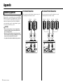
Connecting Speakers............................................................22
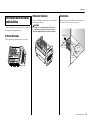
Vertical/Horizontal Orientation and Installation .....................23
Rack Mounting ......................................................................24
Effect Programs ....................................................................25
Jack and Plug List.................................................................26
Dimensions ...........................................................................26
General Specifications ..........................................................27
Index................................................................................... 28
Contents
Complete Range of Input Channels
This model is equipped with four mono input channels (channels 1 to 4) and four mono/stereo input channels (channels
5/6 to 11/12).
Up to eight microphones can be connected. Line-level devices such as keyboards and CD players can also be connected
to each channel. In addition, channel 4 can be used with Hi-Z inputs used to directly connect an instrument such as a
guitar or bass guitar.
Compressor
This product is equipped with the popular 1-knob COMP function used in MGP and MG series models. By simply
operating a single control, it is possible to get optimal compression for vocals and instruments.
Comprehensive, Professional Effects and Signal Processing
This product is equipped with a powerful, comprehensive DSP section that provides the following effects and proces-
sors:
• A total of 24 different effects that are in the same league as our famed SPX effect processor series used by profes-
sionals. (See page 11.)
• A feedback suppressor, which automatically prevents undesirable feedback noise. (See section @4 on page 13.)
• A Flex-type graphic equalizer (Flex9GEQ) that allows you to select up to nine bands out of a total of 31 for fine tun-
ing. (See page 19.)
• A speaker processor that allows the connected speakers to be used to their full performance potential. (See page 16.)
High Efficiency Class-D Amplifier
This model has a built-in high efficiency power amplifier. Despite its low power consumption, it is capable of high vol-
ume output while remaining relatively lightweight.
It also has a built-in overload protection function to improve reliability.
Rack Mounting
This product can be mounted onto a 19-inch rack by using the RK-EMX7 (rack-mount brackets) sold separately.
Main Features
Accessories (Please check that they are included with your mixer.)
• AC power cord (2.5 m)
• Technical Specifications (English only): Includes general specifications, input/output characteristics, and a block
diagram.
• Owner’s Manual (this document)

8
EMX7 Owner’s Manual
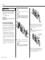
Quick Start Guide
Getting Sound to the Speakers/
Connection Example
NOTICE
Do not bundle or tie the power cord and speaker cables dur-
ing use. Due to the large current flowing through the speaker
cables, it may lead to acoustic noise or electromagnetic inter-
ference.
3.
2.
Passive
speakers
Rear Panel (See page 14.)
AC power
cord
1. Turn off ( ) all switches (including the
[ ] (Power) switch).
2. Connect the devices you intend to use.
(The diagram to the right shows a connection example.
Also refer to the diagram to the left.)
Precautions for Connecting the Speakers
• Connect a single passive speaker (a speaker without an
internal amplifier) to the respective [SPEAKERS A/B]
jacks. Sending the signal from both [SPEAKERS A/B]
jacks to a single speaker may result in malfunction.
• Make sure to insert the speaker cables all the way inside
until secure. When connecting a speakON plug, insert it all
the way inside, then turn until it locks in place.
• Use speaker cables that have insulated connector handles
(housing).
• For details about speaker connection, see page 22.
3. Connect the included power cord.
Connection order:
Mixer [AC IN] jack Power outlet
4. Turn all [LEVEL] controls and MASTER
[LEVEL] controls to “0” and set the equal-
izer controls to the “ ” position.
5. Set the [ MIC/ LINE] switch to the
“ MIC” position for microphone con-
nection, and to the “ LINE” position for
connection of an instrument or audio
device. When connecting a condenser
microphone, set the [PHANTOM +48V]
switch to the ON position ( ).
NOTE
When removing the power cord, do so in the reverse order.
(Power outlet Mixer [AC IN] jack)
t
Microphone
× 3
Electric bass guitar
Keyboard
Turn the [Hi-Z] switch on.
(See section i on page
12.)
Equalizer
controls
Connection
Example

Quick Start Guide
9
EMX7 Owner’s Manual
Portable audio
player
Passive speakers
Power amplifier
NOTE
Normally, speakers are connected via
the [SPEAKERS A/B] jacks on the rear
panel. However, if a higher output level
is required, or if you want to add more
speakers, connect the speakers via a
power amplifier that is connected to
the [STEREO OUT] jack.
6. Turn on the power.
Switching order:
Instrument or audio device Mixer [ ] (Power) switch
7. Set the [LEVEL] control for the channel that has the connected
device to the “ ” position.
8. Use the STEREO MASTER [LEVEL] control to adjust the overall
sound level.
9. If necessary, adjust the level balance of the connected devices
using the [LEVEL] controls for channels 1 to 11/12.
WARNING
When turning off the power, a loud and unpleasant noise may be generated by
the speakers. To prevent this, first turn off the Mixer [ ] (Power) switch, then
turn off the instrument or audio device.
t
Optimizing the volume settings
When the volume is too loud
Turn the [LEVEL] control to the minimum (zero). Set the [ MIC/ LINE] switch to
the “ LINE” position, and then slowly raise the [LEVEL] control until the desired
volume is reached.
When the volume is too soft
Turn the [LEVEL] control to the minimum (zero). Set the [ MIC/ LINE] switch to
the “ MIC” position, and then slowly raise the [LEVEL] control until the desired vol-
ume is reached.

Quick Start Guide
10
EMX7 Owner’s Manual
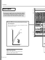
Using the Compressor
When the compressor is applied to vocals, it evens out the input level, reducing the
level of loud passages and bringing up softer passages. It also makes each sound
more distinct, enabling the listener to better understand the performer’s singing.
1. Adjust the [COMP] controls until you get the desired sound for channels you
wish to add compression.
Turn the control to the right to increase the level of compression. Avoid setting the value too high, as too
much compression may lead to feedback.
Common Compressor Applications
In addition to vocals, the compressor can be used to enhance the sound of
instruments such as guitars, bass guitars, and drums.
0
10
Output
(Max)
(Min)
Input

Quick Start Guide
11
EMX7 Owner’s Manual
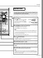
Using the Built-in Effects
It is possible to add particular sound effects or effects that simulate the sound of different perfor-
mance environments, such as concert halls and small clubs.
1. Call up the HOME screen.
When the [ ] (Power) switch is turned on ( ), the HOME
screen is displayed. (See the figure to the right.) If a different
screen is displayed, it will come up as soon as the [PROGRAM]
rotary encoder is operated.
2. Use the [PROGRAM] rotary encoder to select the desired effect.
q Turn the [PROGRAM] rotary encoder to select the program.
w Press the [PROGRAM] rotary encoder to confirm your selection.
3. Turn on ( ) the FX RTN [FX ON] switch.
The switch lights up to indicate that it is on. Connect a control device such as the optional FC5 foot switch (sold separately)
to the [FOOT SW] jack, which lets you conveniently bypass/enable the built-in effects.
4. Set the FX RTN [LEVEL] control to the “ ” position.
5. Use the [AUX2/FX] send controls to adjust the effect depth for each channel you wish to apply
the effect.
6. Use the FX RTN [LEVEL] control to adjust the overall effect depth.
Program number
Program name
NOTE
• You can also select and confirm the program by simultaneously holding down and turning the [PROGRAM] rotary encoder.
• If no operation is detected for an extended period of time, and the selected program is not confirmed, the system will auto-
matically return to the previously confirmed program.
• For details about available effects, refer to the “Effect Programs” on page 25.
t
NOTE
If you wish to change effect parameters such as reverb time or delay time, adjust the FX RTN [PARAMETER] control. (See
section !2 on page 12.) For details about the parameters of each effect that can be adjusted with the FX RTN [PARAMETER]
control, refer to the “Effect Programs” on page 25.

12
EMX7 Owner’s Manual
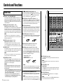
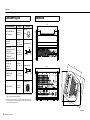
Controls and Functions
q Equalizer controls [HIGH]/[MID]/[LOW]
For adjusting the [HIGH], [MID], and [LOW] audio frequencies. Turn-
ing the control to the right amplifies (boosts) the corresponding fre-
quency band, while turning to the left attenuates (cuts) the band.
Setting the control to the “t” position produces a flat response in the
corresponding band.
w [AUX1] send controls (Channels 1 – 11/12)
[AUX2/FX] send controls (Channels 1 – 11/12)
For adjusting the levels of each signal sent to the AUX1 and AUX2/
FX (built-in effects) buses from each channel independently. On
channels 5/6 to 11/12, the Line L (odd) and Line R (even) input sig-
nals are mixed before being sent into the AUX1 and AUX2/FX buses.
Adjust the controls so that they are near the “t” (nominal) position.
e [LEVEL] controls (Channels 1 – 11/12)
Signal indicators (Channels 1 – 11/12)
For adjusting the volume for each channel. When each channel
receives an input signal, the signal indicator lights up. To reduce
noise, set all [LEVEL] controls on unused channels to the minimum.
r [COMP] controls
For adjusting the amount of compression applied to the correspond-
ing channel. As the [COMP] control is turned to the right, the thresh-
old, ratio, and output gain are adjusted simultaneously.
t [PHANTOM +48V] switch
Turn this switch on ( ) to supply all the XLR input jacks (channels
1 to 11/12) with DC +48 V phantom power. Turning on the switch
supplies power to condenser microphones or a DI (direct injection
box). When it is on, the switch lights up.
Front Panel
NOTE
The [AUX1] send control is a PRE setting that is not affected by the
[LEVEL] control, and the [AUX2/FX] send control is a POST setting that is
affected by the [LEVEL] control.
NOTE
Avoid raising the level of the [COMP] control too high, as the higher aver-
age output level that results may lead to feedback.
NOTICE
Follow the important precautions below, in order to prevent noise
and possible damage to external devices and the mixer when you
operate this switch.
• If you do not need phantom power, or when you connect a device
that does not support phantom power, be sure to leave this switch
off or connect via the phone (channels 1 to 7/8) / RCA-pin (9/10
and 11/12) / stereo mini (11/12) plugs.
• Do not connect or disconnect cables while this switch is on.
•Turn @3 AUX1, AUX2, and STEREO MASTER [LEVEL] controls to
the minimum setting before operating this switch.
y [ MIC/ LINE] switches (Channels 1 – 4)
For channels with low-level input signal devices such as micro-
phones, set the switches to the “ MIC” position. For channels with
high-level input signals such as electronic instruments and audio
devices, set the switch to the “ LINE” position.
u [HPF] (High Pass Filter) switches (Channels 1 – 3)
Turning this switch on ( ) applies a high-pass filter that attenuates
frequencies below 80 Hz in the signal by a slope of 12 dB/octave.
This function should be kept on when using vocals in order to reduce
noise from vibration or wind picked up by the microphone.
i [Hi-Z] switch (Channel 4)
Turn this switch on ( ) when you wish to connect instruments with
passive pickups such as acoustic-electric guitars or electric bass
guitars that do not have internal batteries. It enables such devices to
be directly connected to the mixer without the need for a DI (direct
injection box). This function affects only the phone jack input.
o [MIC/LINE] input jacks (Channels 1 – 4)
For connecting microphones, guitars, electronic musical instruments
or audio devices. These are compatible with both XLR and phone
plugs.
!0 [MIC] input jacks (Channels 5/6, 7/8, 9/10, 11/12)
These are balanced XLR microphone input jacks.
!1 [LINE] input jacks (Channels 5/6, 7/8, 9/10, 11/12)
For connecting line-level devices such as electronic instruments,
acoustic-electric guitars, CD players, and portable audio players.
These are compatible with TS phone, RCA-pin, and stereo mini
plugs. Using only the [L/MONO] jacks results in the stereo left and
right channels outputting the same signal.
• Channels 5/6, 7/8: TS phone
• Channel 9/10: RCA-pin
• Channel 11/12: RCA-pin, stereo mini
!2 FX RTN (Effect Return) [PARAMETER] control
For adjusting parameters (depth, speed, etc.) for the selected effect
program. The last value used with each effect program is saved.
NOTE
If desired, a single channel’s [LINE] and [MIC] jacks can be used together
at the same time. But note that the levels cannot be adjusted indepen-
dently. The stereo mini jack has priority for channel 11/12 [LINE] input jack.
NOTE
When you change to a different effect type, the mixer automatically
restores the value that was previously used with the newly selected effect
(regardless of the current position of the FX RTN [PARAMETER] control).
XLR Phone
RCA-pin Stereo mini
!3 FX RTN [AUX1] send control
For adjusting the level of the signal sent from the built-in effect unit to
the AUX1 bus.
!4 FX RTN [LEVEL] control
Signal indicator
For adjusting the level of the effect sent from the built-in effect unit to
the STEREO L/R bus. The signal indicator lights up when a signal is
received by the built-in effect unit.
!5 FX RTN [FX ON] switch
For turning the corresponding built-in effect on or off. It lights up
when it is switched on ( ).
NOTE
The FX RTN [LEVEL] control does not affect the level of the signal sent to
the AUX1 bus.
NOTE
If this switch is on and the foot switch (see “!6 FX RTN [FOOT SW] jack”)
is used to mute the built-in effect, the switch flashes.
q
w
r
o
yu i
!0
t
e
yu yu y
#4
!1

Controls and Functions
13
EMX7 Owner’s Manual
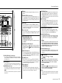
!6 FX RTN [FOOT SW] (Foot Switch) jack
For connecting an unlatched-type foot switch such as the Yamaha
FC5. It is useful for solo performers, since it allows you to mute the
effects with your foot.
!7 Effect program list
This is a convenient on-panel list of the built-in effect programs. For
details about these programs, see the “Effect Programs” on page 25.
!8 [PROGRAM] rotary encoder
For selecting one of the 24 built-in effects. Turn the rotary encoder to
select the desired effect, and then press the encoder to enable it.
NOTE
You can also select the desired effect by turning the rotary encoder while
holding it down.
!9 Display
Shows the currently used program and settings screens for each
function.
@0 [MENU/CONTROL] rotary encoder
For operating and configuring the SPEAKER PROCESSOR screen
or SYSTEM SETUP screen, and setting the graphic equalizer. Turn
the rotary encoder to select the desired setting, and then press the
encoder to enable it.
@1 Level meter
This uses LED indicators to show the STEREO L/R, AUX1, and
AUX2 signal levels. The “0” ( ) segment corresponds to the nominal
output level. The “PEAK” segment on the level meter lights when
output reaches the clipping level.
@2 Level meter switch
This selects which signal is sent to the level meter. You can use this
switch to select the signal from the STEREO L/R, AUX1, or AUX2
buses.
@3 AUX1 MASTER [LEVEL] control
AUX2 MASTER [LEVEL] control
STEREO MASTER [LEVEL] control
For adjusting the level of the signals sent to the AUX1, AUX2, and
STEREO L/R.
@4 [FEEDBACK SUPPRESSOR] switch
When this switch is on ( ), it lights up to indicate that feedback is
automatically suppressed. (This utilizes a seven-band notch filter.
When this switch or the [ ] (Power) switch is off, the notch filter will
be reset.)
@5 [GEQ ACCESS] buttons
These buttons bring up the graphic equalizer (GEQ) setting screen.
Press the [GEQ ACCESS] button corresponding to the channel that
you wish to use (AUX1, AUX2 or STEREO). Unlike other switches,
these buttons cannot be locked.
@6 [STANDBY] switch
When this switch is turned on ( ), it lights up and all inputs for
channels 1 to 7/8 are muted. Please note that channels 9/10 and 11/
12 are not muted. This is an added convenience for playing back-
ground music during gaps in the performance.
@7 [AUX1 SEND] jack
[AUX2 SEND] jack
For connecting to a musician monitoring system, external effect
device, and so on. These are impedance balanced TRS phone type
output jacks. (See the “Jack and Plug List” on page 26.)
@8 [STEREO OUT] jacks
These are TRS phone type impedance balanced output jacks that
output the mixed stereo signal. The signal level is adjusted by the
STEREO MASTER [LEVEL] control before it is output. Using only
the [L/MONO] jack lets you obtain a signal composed of the left and
right channels mixed together.
@9 [REC OUT] jacks
These are unbalanced RCA-pin output jacks. They can be used to
connect an external recorder. The output signal from these jacks is
not affected by the STEREO MASTER [LEVEL] control or graphic
equalizer settings. The recording level can be separately adjusted on
the recording device.
#0 AMPLIFIER [PROTECTION] indicators
Lights up to indicate amplifier protection is operating. The “CH A”
indicator is for the signal sent to the [SPEAKERS A] jack. The “CH
B” indicator is for the signal sent to the [SPEAKERS B] jack.
#1 AMPLIFIER [LIMIT] indicators
These light up when the DSP amplifier protection limiter is operating.
The “CH A” indicator is for the signal sent to the [SPEAKERS A] jack.
The “CH B” indicator is for the signal sent to the [SPEAKERS B]
jack.
#2 AMPLIFIER [MODE] indicators
These indicate whether “STEREO” or “L+R/AUX1” mode is currently
selected. For more information about selecting the amplifier mode,
see page 17.
#3 [ ] (Power) switch
For turning the power ON ( ) or OFF ( ).
#4 Vents
There are vents located on both sides of the mixer, and a cooling fan
is installed on the exhaust side. Do not block the vents on either side
when using the mixer.
NOTICE
If used at a very high volume such that the indicators flash continu-
ously, the internal power amplifier section will be excessively over-
loaded and may malfunction. Reduce the output level with the AUX1
and STEREO MASTER [LEVEL] controls so that the indicators flash
only briefly on the highest transient peaks.
WARNING
Please note that trace current can continue to flow even when the
[ ] (Power) switch is in the OFF position. If you do not plan to use
the mixer for an extended period of time, be sure to unplug the
power cord from the wall outlet.
NOTICE
Rapidly turning the [ ] (Power) switch on and off in succession
may cause it to malfunction. After turning the mixer OFF, wait for
about 10 seconds before turning it ON again.
@7
@5
!6
!5
!2
!9
!7
@1
!3
@6
#2
#3
#1
#0
!4
!8
@3
@4
@0
@9@8
#4
@2

Controls and Functions
14
EMX7 Owner’s Manual
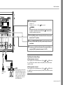
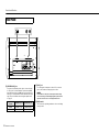
#5 [SPEAKERS A/B] jacks
Use commercially available speaker cables to connect the speak-
ers. These jacks can be used with both TS phone and speakON
plugs. When connecting a speakON plug, insert it and turn until it
locks in place. The amplifier mode selection determines the output
signal. For more information about selecting the amplifier mode,
see page 17.
#6 [AC IN] jack
For connecting the included power cord here. First, connect the
power cord to the mixer, and then plug it into an outlet.
#7 [USB] terminal
This is used only for performing maintenance. It is not used during
normal operation.
Rear Panel
#5
#6
#7
Amplifier Mode
Selection
[SPEAKERS A] Jack [SPEAKERS B] Jack
STEREO STEREO L signal STEREO R signal
L+R/AUX1 L+R signal AUX1 signal
NOTICE
Do not bundle or tie the power cord and speaker cables during
use. Due to the large current flowing through the speaker cables, it
may lead to acoustic noise or electromagnetic interference.

15
EMX7 Owner’s Manual
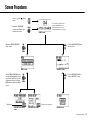
Screen Procedures
MENU button
Turn the [MENU/CONTROL] rotary
encoder until it highlights the opera-
tion you wish to perform. Press it to
confirm your selection. (Select the
MENU button to return to the MENU
screen.)
Operate the [MENU/CONTROL]
rotary encoder.
SPEAKER PROCESSOR
screen
SYSTEM SETUP screen GEQ ON screen
GEQ EDIT screenMENU screen
(* Firmware version information)
Press the GEQ ACCESS button.
(From the GEQ EDIT screen)
Press the [GEQ ACCESS] button
from any screen.
(*)
Turn on ( ) the [ ] (Power)
switch.
Operate the [PROGRAM]
rotary encoder. (Can be oper-
ated from any screen.)
HOME screen*
* The currently selected effect is dis-
played on the HOME screen. For
details about effect selection, see
“Using the Built-in Effects” on page 11.

16
EMX7 Owner’s Manual
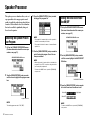
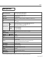
Speaker Processor
The speaker processor function allows you to set
a program that selects an appropriate sound
quality to match the particular speakers that are
connected. It also includes a bass boost function
that can be enabled to significantly bring out
those lower frequencies.
1. Call up the SPEAKER PROCESSOR screen.
(For more information about the screen pro-
cedures, see page 15.)
2.Turn the [MENU/CONTROL] rotary encoder
until the cursor highlights the program name
box.
Selecting the Speaker Proces-
sor Program
NOTE
The default program name box is FLAT (OFF).
SPEAKER PROCESSOR screen
Program name box
3.Press the [MENU/CONTROL] rotary encoder
to bring up the program list.
4.Turn the [MENU/CONTROL] rotary encoder to
select the desired program. Press it to con-
firm your selection.
NOTE
• The program list is automatically closed if no operation is
detected for an extended period of time.
• The program list includes the names of common Yamaha
speakers, etc.
NOTE
• When using a model of speaker that is not included in the
program list, select FLAT, or any other setting that satisfies
your sound quality requirements.
• To return to the HOME screen, operate the [PROGRAM]
rotary encoder.
1. Call up the SPEAKER PROCESSOR screen.
(For more information about the screen pro-
cedures, see page 15.)
2.Turn the [MENU/CONTROL] rotary encoder
until the cursor highlights the BASS BOOST
ON button.
3.Press the [MENU/CONTROL] rotary encoder
to turn the bass boost function on or off.
Turning the Bass Boost Func-
tion ON/OFF
NOTE
To return to the HOME screen, operate the [PROGRAM]
rotary encoder.
SPEAKER PROCESSOR screen
BASS BOOST ON button
(Highlighted)When ON
When OFF

17
EMX7 Owner’s Manual
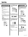
System Setup
There are two amplifier modes:
• STEREO:
When using the SPEAKERS A/B channel for L/R stereo. Pro-
vides common 2-channel stereo output.
• L+R/AUX1:
When using the SPEAKERS A channel for L+R mono, and
the SPEAKERS B channel for AUX1. The L+R signal is sent
to the main speaker and the AUX1 signal is sent to the moni-
tor speaker for the performers.
1. Call up the SYSTEM SETUP screen. (For more
information about the screen procedures, see
page 15.)
Selecting the Amplifier Mode
CAUTION
When selecting the amplifier mode, set the AUX1 and
STEREO MASTER [LEVEL] controls to “0.” This prevents
excessive output from the [SPEAKERS A/B] jacks when
switching the amplifier mode.
SYSTEM SETUP screen
2.Turn the [MENU/CONTROL] rotary encoder
until the cursor highlights the AMP MODE
parameter box.
3.Press the [MENU/CONTROL] rotary encoder
so that the parameter box is fully highlighted.
4.Turn the [MENU/CONTROL] rotary encoder to
change the Amp Mode parameter. You can
choose between STEREO and L+R/AUX1
modes.
5.Press the [MENU/CONTROL] rotary encoder
to confirm your selection.
The AMPLIFIER [MODE] indicators on the front panel
show the current amplifier mode. (See section #2 on page
13.)
NOTE
To return to the HOME screen, operate the [PROGRAM]
rotary encoder.
Parameter box
1. Call up the SYSTEM SETUP screen. (For more
information about the screen procedures, see
page 15.)
2.Turn the [MENU/CONTROL] rotary encoder
until the cursor highlights the CONTRAST
parameter box.
3.Press the [MENU/CONTROL] rotary encoder
so that the parameter box is fully highlighted.
4.Turn the [MENU/CONTROL] rotary encoder to
set the Contrast parameter. The contrast can
be set to any value from 0 to 10, providing 11
different contrast levels.
Setting the LCD Contrast
SYSTEM SETUP screen
Parameter box

System Setup
18
EMX7 Owner’s Manual
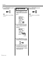
5.Press the [MENU/CONTROL] rotary encoder
to confirm your selection.
NOTE
To return to the HOME screen, operate the [PROGRAM]
rotary encoder.
1. Call up the SYSTEM SETUP screen. (For more
information about the screen procedures, see
page 15.)
2.Turn the [MENU/CONTROL] rotary encoder
until the cursor highlights the BACKLIGHT
parameter box.
3.Press the [MENU/CONTROL] rotary encoder
so that the parameter box is fully highlighted.
4.Turn the [MENU/CONTROL] rotary encoder to
set the Backlight parameter. The brightness
can be set to any value from 0 to 3, providing
4 different brightness levels.
Setting the LCD Backlight
SYSTEM SETUP screen
Parameter box
5.Press the [MENU/CONTROL] rotary encoder
to confirm your selection.
NOTE
To return to the HOME screen, operate the [PROGRAM]
rotary encoder.

19
EMX7 Owner’s Manual
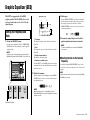
Graphic Equalizer (GEQ)
The EMX7 is equipped with a Flex9GEQ
graphic equalizer. The Flex9GEQ allows you to
select up to nine bands out of a total of 31 and
adjust the gain.
1. Call up the GEQ EDIT screen.
Press the corresponding AUX1, AUX2 or STEREO [GEQ
ACCESS] button for the channel that you wish to apply the
graphic equalizer.
Setting the Frequency and
Gain
NOTE
If another screen is being displayed, press the appropriate
[GEQ ACCESS] button until the GEQ EDIT screen comes up.
[GEQ ACCESS] button
q Frequency
This shows the frequency of the currently selected band.
(Unit: Hz)
w Gain
This displays the gain value of the currently selected band.
(Unit: dB)
e Graphical representation
This illustrates the current settings.
r Number of available bands
Since the EMX7 uses a Flex9GEQ graphic equalizer (with
maximum of 9 bands), this shows the number of remaining
bands that can be set.
2.Select the frequency.
When the frequency value is highlighted, turn the [MENU/
CONTROL] rotary encoder to select the desired frequency
(for adjusting the gain).
NOTE
When the frequency value is not highlighted, press the
[MENU/CONTROL] rotary encoder to highlight it, and enable
frequency selection.
GEQ EDIT screen
q w
e
r
3.Set the gain.
Press the [MENU/CONTROL] rotary encoder to highlight
the Gain parameter and enable setting of the gain value for
the frequency previously selected in Step 2. Turn the
[MENU/CONTROL] rotary encoder to set the gain for the
corresponding frequency.
4.If necessary, repeat Steps 2 and 3 until the
graphic equalizer has been set as needed.
Resetting the Gain for the Selected
Frequency
Press and hold down the [MENU/CONTROL] rotary encoder
for at least two seconds to reset the gain to “0.0” for the selected
frequency.
NOTE
To return to the HOME screen, operate the [PROGRAM]
rotary encoder.
NOTE
Both the frequencies and the gain can be reset using the [MENU/
CONTROL] rotary encoder.

Graphic Equalizer (GEQ)
20
EMX7 Owner’s Manual
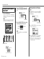
1. Call up the GEQ ON screen.
Press the corresponding AUX1, AUX2 or STEREO [GEQ
ACCESS] button for the channel that you wish to apply the
graphic equalizer.
Turning the Graphic Equalizer
(GEQ) ON/OFF
NOTE
If another screen is shown, press the appropriate [GEQ
ACCESS] button until the GEQ ON screen is called up.
[GEQ ACCESS] button
GEQ ON screen
2.Turn the [MENU/CONTROL] rotary encoder
until the cursor highlights the GEQ ON but-
ton.
3.Press the [MENU/CONTROL] rotary encoder
to turn the graphic equalizer on or off.
NOTE
To return to the HOME screen, operate the [PROGRAM]
rotary encoder.
GEQ ON button
(Highlighted)When ON
When OFF
Resetting the Gain for All Frequen-
cies
1. When the GEQ ON screen is displayed, turn the [MENU/
CONTROL] rotary encoder until the cursor highlights the
RESET GEQ button.
2.Press the [MENU/CONTROL] rotary encoder to bring up
the following confirmation screen.
3.Turn the [MENU/CONTROL] rotary encoder until the cur-
sor highlights the OK button. Press the [MENU/CON-
TROL] rotary encoder to confirm your selection. All gain
values will then be reset. (Select the CANCEL button to
cancel the reset procedure.)
RESET GEQ button
Sidan laddas ...
Sidan laddas ...
Sidan laddas ...
Sidan laddas ...
Sidan laddas ...
Sidan laddas ...
Sidan laddas ...
Sidan laddas ...
Sidan laddas ...
Sidan laddas ...
Sidan laddas ...
Sidan laddas ...
-
 1
1
-
 2
2
-
 3
3
-
 4
4
-
 5
5
-
 6
6
-
 7
7
-
 8
8
-
 9
9
-
 10
10
-
 11
11
-
 12
12
-
 13
13
-
 14
14
-
 15
15
-
 16
16
-
 17
17
-
 18
18
-
 19
19
-
 20
20
-
 21
21
-
 22
22
-
 23
23
-
 24
24
-
 25
25
-
 26
26
-
 27
27
-
 28
28
-
 29
29
-
 30
30
-
 31
31
-
 32
32


på andra språk
- italiano: Yamaha EMX7 Manuale del proprietario
- čeština: Yamaha EMX7 Návod k obsluze
- español: Yamaha EMX7 El manual del propietario
- Deutsch: Yamaha EMX7 Bedienungsanleitung
- polski: Yamaha EMX7 Instrukcja obsługi
- português: Yamaha EMX7 Manual do proprietário
- français: Yamaha EMX7 Le manuel du propriétaire
- Türkçe: Yamaha EMX7 El kitabı
- English: Yamaha EMX7 Owner's manual
- dansk: Yamaha EMX7 Brugervejledning
- русский: Yamaha EMX7 Инструкция по применению
- suomi: Yamaha EMX7 Omistajan opas
- Nederlands: Yamaha EMX7 de handleiding
- română: Yamaha EMX7 Manualul proprietarului
Relaterade papper
-
Yamaha EMX5 Bruksanvisning
-
Yamaha EMX2 Bruksanvisning
-
Yamaha DSR215 Bruksanvisning
-
Yamaha MGP16X/MGP12X Användarmanual
-
Yamaha XMV4140-D Bruksanvisning
-
-
Yamaha TX6n/TX5n/TX4n Bruksanvisning
-
Yamaha QL1 Bruksanvisning
-
Yamaha V3 Bruksanvisning
-