Yamaha DPX-1300 Bruksanvisning
- Kategori
- Dataprojektorer
- Typ
- Bruksanvisning

YAMAHA ELECTRONICS CORPORATION, USA 6660 ORANGETHORPE AVE., BUENA PARK, CALIF. 90620, U.S.A.
YAMAHA CANADA MUSIC LTD. 135 MILNER AVE., SCARBOROUGH, ONTARIO M1S 3R1, CANADA
YAMAHA ELECTRONIK EUROPA G.m.b.H. SIEMENSSTR. 22-34, 25462 RELLINGEN BEI HAMBURG, GERMANY
YAMAHA ELECTRONIQUE FRANCE S.A. RUE AMBROISE CROIZAT BP70 CROISSY-BEAUBOURG 77312 MARNE-LA-VALLEE CEDEX02, FRANCE
YAMAHA ELECTRONICS (UK) LTD. YAMAHA HOUSE, 200 RICKMANSWORTH ROAD WATFORD, HERTS WD18 7GQ, ENGLAND
YAMAHA SCANDINAVIA A.B. J A WETTERGRENS GATA 1, BOX 30053, 400 43 VÄSTRA FRÖLUNDA, SWEDEN
YAMAHA MUSIC AUSTRALIA PTY, LTD. 17-33 MARKET ST., SOUTH MELBOURNE, 3205 VIC., AUSTRALIA
Printed in Japan WF80500
C2005 All Rights Reserved.
DPX-1300
G
BEDIENUNGSANLEITUNG
DIGITAL CINEMA PROJECTOR
PROJECTEUR CINEMA NUMERIQUE
DPX-1300
10_DPX-1300-Cover1-4_G.p65 9/22/05, 4:34 PM1

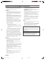
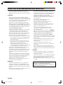
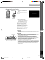
Caution: Read this before operating this unit.
•To assure the finest performance, please read this manual
carefully. Keep it in a safe place for future reference.
Installation
• Install this unit in a well-ventilated, cool, dry, clean place with
at least 30 cm (1 feet) clearance on the top, right and left, and
at the back of this unit — away from direct sunlight, heat
sources, vibration, dust, moisture, and/or cold.
• Locate this unit away from other electrical appliances, motors,
or transformers to avoid humming sounds. To prevent fire or
electrical shock, do not place this unit where it may get
exposed to rain, water, and/or any type of liquid.
• Do not expose this unit to sudden temperature changes from
cold to hot, and do not locate this unit in an environment with
high humidity (i.e. a room with a humidifier) to prevent
condensation inside this unit, which may cause an electrical
shock, fire, damage to this unit, and/or personal injury.
• On the top of this unit, do not place:
– Other components, as they may cause damage and/or
discoloration on the surface of this unit.
– Burning objects (i.e. candles), as they may cause fire,
damage to this unit, and/or personal injury.
– Containers with liquid in them, as they may cause electrical
shock to the user and/or damage to this unit.
• Do not cover this unit with a newspaper, tablecloth, curtain, etc.
in order not to restrict heat dissipation. If the temperature
inside this unit rises too much, it may cause fire, damage to this
unit, and/or personal injury.
•When installing this unit on the ceiling, make sure the ceiling
has sufficient strength to support this unit and the ceiling
mounts for an extended period of time. Installation must be
performed only by qualified service personnel.
• Install this unit near the AC outlet and where the AC power
plug can be reached easily.
Operation
• Remove the lens cover before starting any operation of this unit
to prevent the heat from staying around the lens. Operation
with the cap on may cause damage to this unit.
• Do not plug in this unit to a wall outlet until all connections are
complete.
• Only the voltage specified on this unit must be used. Using this
unit with a higher voltage than specified is dangerous and may
cause fire, damage to this unit, and/or personal injury.
YAMAHA will not be held responsible for any damage
resulting from use of this unit with a voltage other than that
specified.
• Do not use force on switches, knobs and/or cords.
•Take care of this unit so that no foreign objects and/or liquid
drop inside this unit.
•To prevent damage by lightning, keep the power cord out and
outdoor antennas disconnected from a wall outlet or te unit
during the lightning storm.
• Do not look into the lens while this unit is turned on. It may
cause serious damage to your eyesight.
• Before moving this unit, press STANDBY/ON to set this unit
in the standby mode, and disconnect the AC power plug from
the wall outlet.
• Do not attempt to modify or fix this unit. Contact qualified
YAMAHA service personnel when any service is needed. The
cabinet should never be opened for any reason.
• When not planning to use this unit for a long period of time
(i.e. vacation), disconnect the AC power plug from the wall
outlet.
•When disconnecting the power cord from the wall outlet, grasp
the plug; do not pull the cable.
• Be sure to read the “Troubleshooting” section on common
operating errors before concluding that this unit is faulty.
Others
• Clean the lens carefully so as not to create any scratches by
using a blower or lens paper.
•Replace the lamp when the LAMP warning indicator blinks in
red after the lamp usage has exceeded 2000 hours. Follow the
lamp replacement procedure described in this manual.
For U.K. customers
If the socket outlets in the home are not suitable for the plug
supplied with this appliance, it should be cut off and an appropriate
3 pin plug fitted. For details, refer to the instructions described
below.
Note
•The plug severed from the mains lead must be destroyed, as a plug with
bared flexible cord is hazardous if engaged in a live socket outlet.
IMPORTANT
THE WIRES IN THIS MAINS LEAD ARE COLOURED IN
ACCORDANCE WITH THE FOLLOWING CODE:
GREEN-AND-YELLOW: EARTH
BLUE: NEUTRAL
BROWN: LIVE
As the colours of the wires in the mains lead of this apparatus may
not correspond with the coloured markings identifying the
terminals in your plug, proceed as follows:
The wire which is coloured GREEN-AND-YELLOW must be
connected to the terminal in the plug which is marked by the letter
E or by the safety earth symbol or coloured GREEN or GREEN-
and-YELLOW.
The wire which is coloured BLUE must be connected to the
terminal which is marked with the letter N or coloured BLACK.
The wire which is coloured BROWN must be connected to the
terminal which is marked with the letter L or coloured RED.
i
10_DPX_1300_cau_G 9/20/05, 5:07 PM1

1
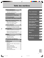
Table of contents
1 Getting started 2
Inappropriate places for installation ....... 2
Accessory check .................................... 2
2 Features 3
3 Controls and functions 4
4 Remote control 6
5 Preparation 10
6 Installation 12
Setting up the DPX-1300 ..................... 12
Projection distance ............................... 13
Projection image position ..................... 14
7 Connection 15
Connecting to AV components ............. 15
Connecting to computer devices ......... 16
8 Projection 17
Checking installation and connections...
17
Turning the projector power on ............ 18
Selecting an input signal ...................... 20
Adjusting the image ............................. 25
9 Menu 27
Menu configurations ............................ 27
Menu items .......................................... 28
Menu operations .................................. 38
10
Memory function
(Saving, Recall, Lock, Copy, Reset) 48
11
Reference 55
Glossary ............................................... 55
Compatible signal types ....................... 56
Maintenance ......................................... 58
Troubleshooting.................................... 60
Message display .................................. 62
LED Indicator meanings ....................... 63
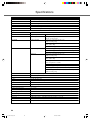
Specifications ....................................... 64
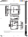
Dimensional drawing ............................ 65
Getting started
Features
Controls and functions
Remote control
Preparation
Projection
Menu
Memory function
Reference
11
10
9
8
7
6
5
4
3
2
1
Connection
Installation
English
11_DPX-1300_E.p65 9/20/05, 5:07 PM1

2
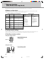
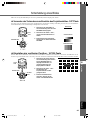
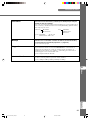
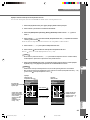
◆Inappropriate places for installation
If this unit is not correctly installed in an appropriate place, it may cause fire or failure, or damage the unit itself. Carefully choose the place
to install this unit by avoiding the places listed below.
1. Places where the temperature and humidity vary greatly
• Do not install this unit in a place where the temperature and humidity become extremely high or the temperature becomes extremely
low.
• This unit must be used within a temperature range of 5 to 35°C.
2. Places without adequate ventilation
• Install this unit with at least 30 cm (1 feet) of ventilation space on the top, right and left, and back.
• Do not cover the ventilation slots of this unit. Covering the slots will obstruct heat dissipation.
• Install this unit on the firm surface.
• Do not cover this unit with a tablecloth, etc.
• Make sure there is nothing to get sucked into the ventilation slots so that the temperature of this unit does not become too high.
• If you are going to install the unit in a rack, be sure to leave space for ventilation to prevent exhaust overheating the unit.
3. Places where it gets dusty
• If the filter is blocked with dust, the temperature of this unit may become too high.
4. Places with too much vibration or impact
•Vibration and impact can damage parts of this unit.
5. Places where this unit gets exposed to water or high humidity
• If this unit is exposed to water or high humidity, it may cause a fire or electrical shock.
6. Unstable places
• If this unit is installed on an unstable or an inclined tabletop, it may fall and cause damage to the unit or personal injury.
7. In close proximity to a Radio or Stereo
•The unit may interfere with reception if placed in close proximity to a radio or television receiver.
Warning
•To ensure vivid, high contrast images, make sure that no light other than the projector light falls directly on the screen.
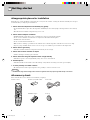
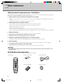
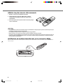
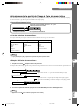
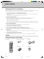
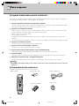
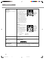
◆Accessory check
Please check that all accessories listed here are included in your package.
• Remote control • Batteries (AA, UM-3 or R6) • Power cable
• Pin/BNC adapters • Lens cap
1 Getting started
45
RESET
6
123
VIDEO
STILL
HIDE
PATTIRIS
AUTO
SETTING
ZOOM FOCUSV. POS
LIGHT
B
D4
DVI
S VIDEO
A
INPUT
MEMORY
HDMI
INPUT
MENU
ASPECT
ESCAPE
11_DPX-1300_E.p65 9/20/05, 5:07 PM2

3
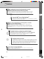
Features
2
English
Adjust 7 colors independently (including white), or use the
automatic color balance function
The DPX-1300 allows you to adjust the 7-axis WRGBYCM color coordinate and gain
parameters directly. For better consistency, you can also control color temperature and RGB
balance together, allowing you to check that the changes you make are always consistent with
your preferences.
The digital interface provides sharp, detailed images
The DPX-1300 is equipped with an HDMI terminal, which is set to become the standard for the
coming generation of products. Connect to a DVD player or set-top box with a HDMI terminal
to receive digital image data directly, and enjoy completely digitally processed images.
Compatible with the content protection function of HDCP.
Intelligent memory functions
The DPX-1300 can store six image memory settings, called memory numbers, for each input
jack. For each memory number, you can set parameters for different input resolutions, and the
unit will switch to the appropriate parameters when it begins displaying an image of an
appropriate resolution. For example, the unit automatically changes display settings without
changing memory numbers when you change from watching a DVD to watching a HDTV
image for which you have set different image menu item parameters.
In-line menus for image adjustment
You can access image adjustment menu items at the touch of a button, and adjust images while
viewing them without opening the menu screen.
Highly configurable electronic adjustment gives you the
freedom to place the projector wherever you want
A short focal length, high power zoom, and fully vertically adjustable lens allow you to use the
projector in a wide range of environments. You can also use the remote control to access many
lens functions such as focus, zoom, and lens shift to fine-tune the projector from your viewing
position.
Uses the DMD
TM
device 720p DarkChip3
TM
The projector uses the high contrast “720p DarkChip3
TM
”, to reduce black levels even further
and reproduce contrasts close to that of a film.
2 Features
11_DPX-1300_E.p65 9/20/05, 5:07 PM3

4
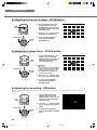
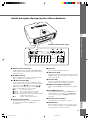
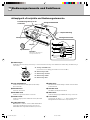
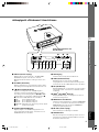
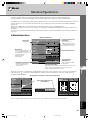
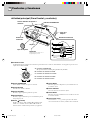
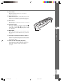
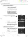
◆Main unit <Front panel and controls>
STANDBY
/
ON
SETTING
LAMP COVER TEMP FAN
PATTERN
ESCAPE
MENU
INPUT
DIGITAL CINEMA PROJECTOR DPX-1300
ASPECT
1
2
3
4
5
1
6
7
8
9
0
STANDBY
/
ON
SETTING
LAMP COVER TEMP FAN
PATTERN
ESCAPE
MENU
INPUT
ASPECT
A
E
B
CD
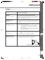
2 STANDBY/ON button
Switches the unit between Standby and On (operational)
modes.
3 ESCAPE button
Exits from submenus.
4 PATTERN button
Switches the built-in test pattern on and off.
5 ASPECT button
Turns the display aspect menu for the project image on and off.
6 (Enter) button
Sets values when the DPX-1300 is displaying the menu. When
the menu is not displayed, the DPX-1300 displays the in-line
image quality adjustment menu. (☞ page 47)
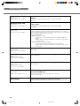
1 LED Indicators
The main unit is equipped with 5 indicators to display various states of operation. See page 63 for explanations of the LED indicator
meanings.
7 MENU button
Switches the settings and adjustments menu display on and off.
8 SETTING button
Selects lens adjustment modes.
9 INPUT button
Switches the input signal selection menu display on and off.
0 Cursor buttons
Use the h, g, +, - buttons for system operations, menu item
selection, and changing system values.
A STANDBY/ON indicator
(There is also an LED on the front panel of the main unit.)
B LAMP warning indicator
C COVER warning indicator
D TEMP warning indicator
E FAN warning indicator
Lamp cover
Ventilation inlet
Adjustable feet
Makes small adjustments to
the projection angle
Lens
Exhaust vent
Front remote control sensor
STANDBY/ON indicator
3 Controls and functions
Lens cap
11_DPX-1300_E.p65 9/20/05, 5:07 PM4

5
Controls and functions
3
English
HDMIDVI
G/Y B/PB/CB R/PR/CR
INPUT A
HD/SYNC
VD
OUT IN
REMOTE
TRIGGER OUT
S VIDEO VIDEO
INPUT B
RGB/YP
BPR/YCBCR
RS-232C
D4 VIDEO
wq
8
765432190
ert
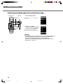
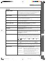
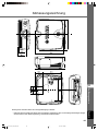
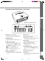
◆Main unit <Rear panel / Connections>
1 INPUT B (D-sub 15 pin)
Receives component video and RGB (RGB/YPBPR/YCBCR)
signals. Use a D-sub monitor cable to connect components to
this jack.
2 D4 VIDEO (D jack)
Receives signals output from the D jacks of other AV
components. It is compatible with D1 - D4 formats.
3 - 7 INPUT A (BNC jacks)
Receive component video and RGB signals. Connect
component signal connectors from AV components to input
jacks 3 - 5, and RGB signal connectors from computers to
input jacks 3 - 7. Use BNC cables for these connections.
3 G/Y (G, or luminance signal)
4 B/P
B/CB (B, or color difference signal)
5 R/P
R/CR (R, or color difference signal)
6 HD/SYNC (Horizontal sync signal, composite sync signal)
7 VD (Vertical sync signal)
8 S VIDEO (Mini DIN jack)
Receives signals from S-VIDEO output jacks of other AV
components. Use an S-VIDEO cable for these connections.
9 AC inlet
Insert the supplied AC power cable here.
0 VIDEO (Pin Jack)
Receives composite video signals from the VIDEO output
jacks of other AV components. Use a video pin cable for these
connections.
q DVI (DVI jack)
Receives RGB signals from computers or AV components. Use
a DVI cable for this connection.
w HDMI
TM
(HDMI
TM
jack)
Receives HDMI
TM
signals from computers or AV components.
e REMOTE IN / OUT jack
Connect the remote control to the REMOTE IN jack if you
want to use it through a cable. The REMOTE OUT jack
outputs the signal received through the REMOTE IN jack
without any change.
r RS-232C (D-sub 9 pin)
For use in servicing this unit.
t TRIGGER OUT
Outputs control signals to external components. This output
provides a potential of 12 V/ maximum 200 mA when this unit
is projecting. Use the supplied trigger-out DC plug (for US
model only) to control external components.
Rear remote control sensor
11_DPX-1300_E.p65 9/20/05, 5:07 PM5

6
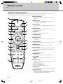
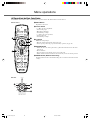
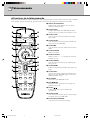
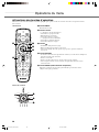
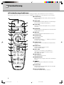
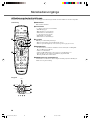
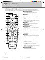
◆ Remote control functions
Buttons on the remote control with identical names to those on the main unit perform identical functions. When using the remote control,
point it at the remote control sensor on the front or back of the main unit from a distance of 7m (23 feet) or less.
1 Transmit indicator
Lights up when the remote control sends infrared signals to the
main unit.
2 AUTO button
Automatically sets the DPX-1300 to the best settings for the
type of signal it is currently receiving.
3 V.POS button
Switches on or off the vertical adjustment mode for the entire
image.
4 ZOOM button
Switches on or off the size adjustment mode for the image the
DPX-1300 is projecting.
5 IRIS button
Switches on or off the lens iris change mode.
6 ESCAPE button
Exits from submenus.
7 Cursor buttons
Use the h ,g, +, - buttons to move the cursor within the on-
screen display.
8 ASPECT button
Turns the display aspect menu for the project image on and off.
9 RESET button
Resets all adjustable parameters to their default settings.
0 STILL button
Stops a moving image, displaying a still of the image the DPX-
1300 is projecting. Press STILL again to cancel this effect.
q INPUT area
Selects the INPUT jacks directly.
w MEMORY area
Calls stored memory (all parameter settings) directly.
e button
Switches the unit between Standby and On (operational)
modes.
r FOCUS button
Switches on or off the focus adjustment mode for the image the
DPX-1300 is projecting.
t PATT (PATTERN) button
Switches on and off the built-in test pattern.
y MENU button
Switches on and off the settings and adjustments menu display.
u (Enter) button
Sets values when the DPX-1300 is displaying the menu. When
the menu is not displayed, the DPX-1300 displays the in-line
image quality adjustment menu. (☞ page 47)
4 Remote control
45
RESET
6
123
VIDEO
STILL
HIDE
PATTIRIS
AUTO
SETTING
ZOOM FOCUSV. POS
LIGHT
B
D4
DVI
S VIDEO
A
INPUT
MEMORY
HDMI
INPUT
MENU
ASPECT
ESCAPE
o
i
u
y
t
p
r
e
1
2
3
4
5
6
7
8
9
0
q
w
11_DPX-1300_E.p65 9/20/05, 5:07 PM6

7
Remote control
4
English
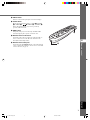
i INPUT button
Switches on and off the input signal selection menu display.
o LIGHT switch
Moving this switch lights the high-use AUTO (2), ESCAPE
(6), ASPECT(8) , (e), MENU (y), and INPUT (i)
buttons. The light disappears if you do not perform any
operation within 10 seconds.
p HIDE button
Temporarily halts projection of the image the DPX-1300 is
currently displaying. Press again to cancel this effect.
a Remote control code switch
Selects ID-1 or ID-2 when operating two main units with one
remote control. You can set the ID for the main unit in the
menu (The default setting is ID-1).
s Remote control cable jack
Connect this jack and REMOTE IN jack on the main unit using
a cable (commercially available) to use the remote control with
a wired connection. (☞ page 8)
INPUT
I
RIS
V
.POS
AU
T
O
PATT
FO
C
US
ZO
O
M
S
E
T
T
I
N
G
I
D-2
ID
-
1
RESET
H
ID
E
ST
I
L
L
S VIDEO
VIDEO
B
D4
A
DVI
4
5
6
1
2
3
HDMI
MEMORY
LIGHT
INPUT
MENU
E
SCAPE
ASPECT
a
s
11_DPX-1300_E.p65 9/20/05, 5:07 PM7

8
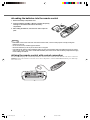
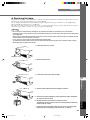
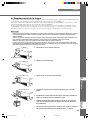
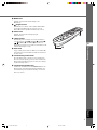
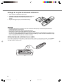
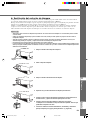
◆Loading the batteries into the remote control
1. Remove the battery compartment cover.
2. Insert two batteries (AA, UM3, or R6 type), matching the polarity
markings on the batteries with those in the battery
compartment.
3. After loading the batteries, close the cover until it snaps into
place.
Warning
• If the remote control must be used closer to the main unit than normal, or does not always operate correctly, exchange the
batteries for new ones.
• Do not mix old and new, or different types of batteries.
• Remove the batteries if you do not plan to use the unit for a long time.
• If the batteries leak, dispose of them immediately, taking care not to touch the battery fluid. If the battery fluid comes into contact
with your eyes, mouth, or skin, rinse it off with water immediately and consult a doctor. Clean the battery compartment thoroughly
before installing new batteries.
◆Using the remote control with a wired connection
Use a 2P monaural miniplug cable (commercially available) to connect the remote control jack on the underside of the remote control to the
REMOTE IN jack on the main unit. Use the wired remote control configuration to control the DPX-1300 without having to be within range
of the remote sensor.
1
3
2
I
R
I
S
V.P O
S
A
U
T
O
PATT
FOCUS
ZOO
M
SE
T
T
I
N
G
ID-2
I
D
-
1
R
ESET
H
IDE
STIL
L
4
5
6
1
2
3
LIGH
T
I
N
PUT
M
E
N
U
ESCAPE
AS
PE
CT
INPUT
INPU
T
S
V
IDE
O
VID
E
O
B
D4
A
D
V
I
HD
MI
HDMIDVI
G/Y B/P
B/CB R/PR/CR
INPUT A
HD/SYNC VD
OUT IN
REMOTE
TRIGGER OUT
S-VIDEO VIDEO
INPUT B
RGB/YPBPR/YCBCR
RS-232C
D4 VIDEO
11_DPX-1300_E.p65 9/20/05, 5:07 PM8

9
Remote control
4
English
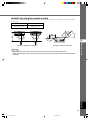
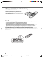
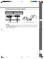
Distance to sensor Angle to sensor
7 m 30˚ vertically and horizontally
(approximate value) (approximate value)
◆ Limits for using the remote control
Use the remote control within the following parameters. The remote control may not function correctly if you use it outside the limits
described here.
Warning
• Bright or fluorescent light on the main unit remote sensor may inhibit the functioning of the remote control.
• Objects placed between the main unit remote sensor and the remote control may block the remote control signal and inhibit
functioning.
Use within a left/right arc of 30 degrees Use within a vertical arc of 30 degrees
HDMI
G/Y B/P
B
/C
B
R/P
R
/C
R
INPUT A
HD/SYNC
VD
OUT IN
REMOTE
TRIGGER OUT
S-VIDEO VIDEO
INPUT B
RGB/YP
B
P
R
/YC
B
C
R
RS-232C
D4 VIDEO
45
RESET
6
123
VIDEO
STILL
HIDE
PATTIRIS
AUTO
SETTING
ZOOM FOCUSV. POS
LIGHT
BDVI
S VIDEO
A
D4
INPUT
MEMORY
HDMI
INPUT
MENU
ASPECT
ESCAPE
45
RESET
6
123
VIDEO
STILL
HIDE
PATTIRIS
AUTO
SETTING
ZOOM FOCUSV. POS
LIGHT
BDVI
S VIDEO
A
D4
INPUT
MEMORY
HDMI
INPUT
MENU
ASPECT
ESCAPE
11_DPX-1300_E.p65 9/20/05, 5:07 PM9

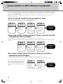
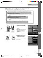
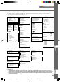
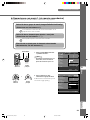
10
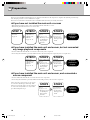
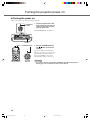
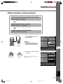
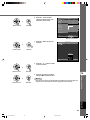
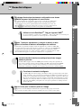
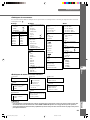
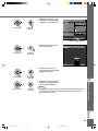
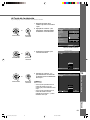
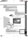
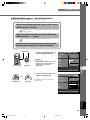
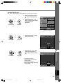
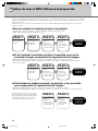
Before projection, install the main unit and a screen, connect the main unit to an AV component or computer, and adjust the projection image.
You can begin projection as soon as installation is complete.
Refer to the sections below for information on how to install the main unit to suit your viewing environment.
◆If you have not installed the main unit or screen
• Immediately after purchase, when you have not installed either the main unit or a screen.
• When moving the main unit and screen to a new location.
◆If you have installed the main unit and screen, and connected a
source component
• You have installed the main unit and screen, and connected source components.
• You are using the main unit in a previously installed location with previously connected source components.
◆If you have installed the main unit and screen, but not connected
any image playback components
• You have installed the main unit and screen, but not connected any source components.
• You are using the main unit in a previously installed location, and wish to change the component you use as a signal source.
You do not need to carry out step 3 or step 4 if you
do not want to adjust the projection image. If the
unit does not project the image correctly, it may not
be connected correctly. In this case, carry out this
procedure starting from step 2.
STEP3
Select an image and
project.
☞ page 17 - 26
• The image is used
for adjusting the
image position
and focus.
STEP4
Adjust the
projection image.
☞ page 27 - 47
• Use the menu to
adjust projection
details.
Projection
preparations
complete
STEP2
Connect AV
components or a
computer to the
main unit.
☞ page 15 - 16
STEP3
Select an image and
project.
☞ page 17 - 26
• The image is used
for adjusting the
image position
and focus.
STEP4
Adjust the
projection image.
☞ page 27 - 47
• Use the menu to
adjust projection
details.
Projection
preparations
complete
STEP 1
Install the main unit
and screen.
☞ page 12
STEP3
Select an image and
project.
☞ page 17 - 26
• The image is used
for adjusting the
image position
and focus.
STEP2
Connect AV
components or a
computer to the
main unit.
☞ page 15 - 16
Projection
preparations
complete
5
Preparation
STEP4
Adjust the
projection image.
☞ page 27 - 47
• Use the menu to
adjust projection
details.
11_DPX-1300_E.p65 9/20/05, 5:07 PM10

11
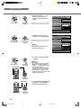
Prepararion
5
English
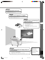
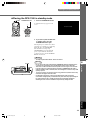
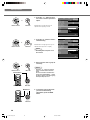
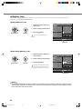
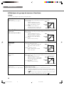
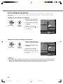
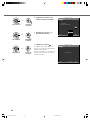
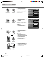
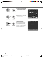
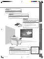
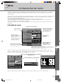
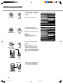
Step2
Connect an AV component or computer
• Connect AV components
• Connect a computer ☞ page 15 - 16
Step3
Turn the power on and selecting an
image for projection
•Turn on the projector power
•Begin playback of the input image
• Select an input signal
• Select a projection image aspect
• Adjust the image
Focus/Vertical and Horizontal position/Size/Iris
☞ page 17 - 26
Step1
Set up the projector and screen
• Install the projector
• Install the screen ☞ page 12 - 14
Only adjust these
parameters when
necessary. It is not
necessary to adjust these
settings once you have set
them initially.
Step4
Use the menu to adjust the image quality and
other parameters
• Image quality: Set image quality details
• Signal setting: Set input signal details
• Default settings: Set the default settings for everyday use
• Installation settings: Set to suit your viewing environment ☞ page 27 - 47
11_DPX-1300_E.p65 9/20/05, 5:07 PM11

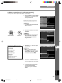
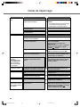
12
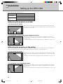
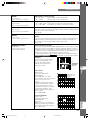
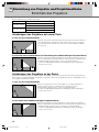
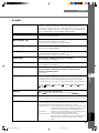
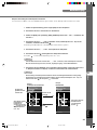
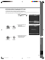
Setting up the DPX-1300
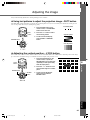
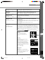
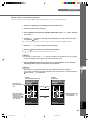
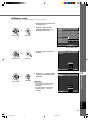
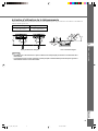
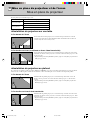
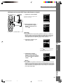
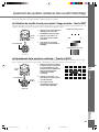
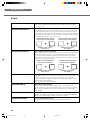
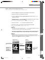
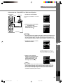
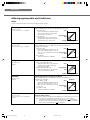
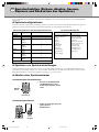
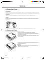
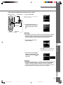
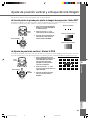
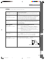
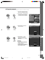
◆ Mounting the projector on a table
A: From in front of a screen
Place the unit on a table to project and view the image from in front of the screen. Usually,
place the unit on a reasonably high table. The height from the bottom of the unit to the center
of the lens is 12.4 cm (4”-7/8).
B: From behind a screen (using a semi-translucent screen)
Place the unit on a table to project and view the image from behind a semi-translucent
screen. The distance between the projector and the screen should be the same as “A: From in
front of the screen”.
• Set the [Location] menu item in the [Setup] menu group to [Rear/Table]. (☞ page 27 - 47)
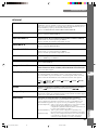
◆ Mounting the projector on the ceiling
There are two kinds of brackets (sold separately: PMT-L31 and PMT-H35), which you can use to mount the projector on the ceiling. Please
consult your dealer for details on their use, and have installation done by either your dealer or a reputable contractor.
C: From in front of a screen
Mount the unit on the ceiling to project and view the image from in front of the screen. The
distance between the projector and the screen should be the same as “A: From in front of the
screen”.
•
Set the [Location] menu item in the [Setup] menu group to [Front/Ceiling]. (☞ page
27 - 47
)
D: From behind a semi-translucent screen
Mount the unit on the ceiling to project and view the image from behind a semi-translucent
screen. The distance between the projector and the screen should be the same as “B: From
behind a screen”.
•
Set the [Location] menu item in the [Setup] menu group to [Rear/Ceiling]. (☞ page
27 - 47
)
There are four ways of mounting the projector.
6
Installation
Mounting method
Placed on a table
Mounted on the
ceiling
Projection method
A: From in front of a screen
C: From in front of a screen
B: From behind a semi-translucent screen
D: From behind a semi-translucent screen
11_DPX-1300_E.p65 9/20/05, 5:07 PM12

13
Installation
6
English
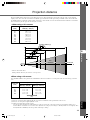
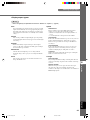
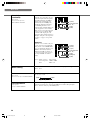
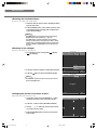
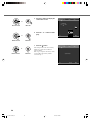
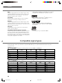
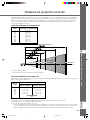
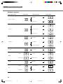
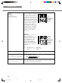
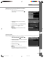
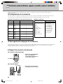
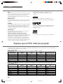
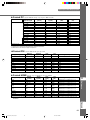
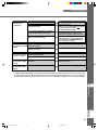
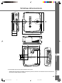
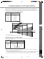
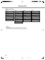
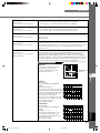
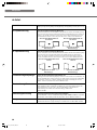
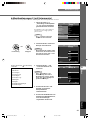
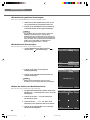
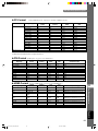
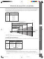
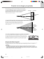
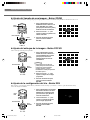
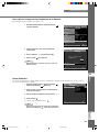
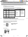
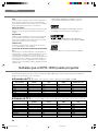
The most suitable distance between the screen and the projector (see Projection distance [a]) depends on the size of the screen (diagonal
length) you use. You can use the zoom function to adjust the projection distance within a preset range from Wide to Tele. You can also alter
the V.POS parameter to adjust the vertical position of the image to better suit the screen. Use the information in the table below to determine
the best location to place the projector in to suit your screen size.
Projection distance
<When using a 4:3 screen>
Since the DPX-1300 has a 16:9 panel, the ideal installation location for use with a 4:3 screen depends on the size of the image you wish to
view.
<When using a 16:9 screen>
60'' 80'' 100'' 150'' 200''
*These are theoretical values.
During actual use there may be a deviance of a few percent.
(*1) Projects a 16:9 image that completely fills the screen (leaves a black line at the top and bottom of the screen).
(*2) Projects a 4:3 image that completely fills the screen.
(*3) When projecting both 16:9 and 4:3 images.
You can use the zoom function to make efficient use of the screen for both *1 and *2 above. The projection distance in this case is
between Wide in *2 and Tele in *1. Use the zoom to adjust the size of the projection images so that they fill the screen completely. Note
that adjustments to V.POS may cause the position of the image to change.
Projection distance [a]
Lens
centerline
Screen size
60
70
80
90
100
110
120
150
200
Screen size
(inch)
1.78 – 2.88
2.08 – 3.37
2.39 – 3.86
2.70 – 4.35
3.00 – 4.84
3.31 – 5.33
3.62 – 5.82
4.54 – 7.29
6.07 – 9.74
Projection distance [a]
Wide (m) – Tele (m)
Screen size
(inch)
16:9 image (*1)
Wide (m) – Tele (m)
4:3 image (*2)
Wide (m) – Tele (m)
Projection distance[a]
60
80
100
120
200
1.63 – 2.64
2.19 – 3.54
2.76 – 4.44
3.32 – 5.34
5.58 – 8.94
2.17 – 3.52
2.93 – 4.72
3.68 – 5.92
4.43 – 7.12
7.43 – 11.92
(*3)
11_DPX-1300_E.p65 9/20/05, 5:07 PM13

14
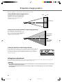
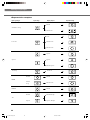
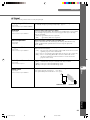
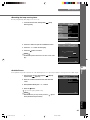
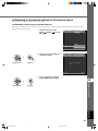
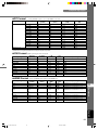
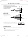
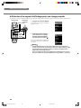
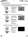
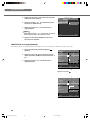
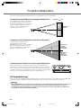
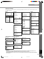
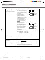
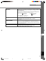
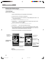
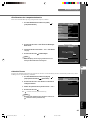
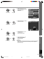
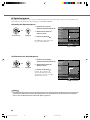
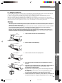
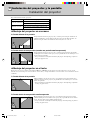
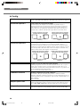
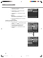
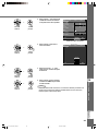
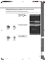
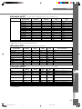
Follow the instructions to adjust the position of the projected image on screen.
<Using ZOOM to adjust image position>
This illustration shows the limits within which the
zoom function can alter projection distance [a] in
relation to screen size. You can adjust the image
within these limits so that it fills the screen
completely. ( ☞ page 26)
<Using V.POS (vertical position) to adjust image position>
You can adjust the vertical position of the
projection image up or down by half of the height
of the screen. For example, shifting V.POS fully up
brings the lower limit of the image above the
centerline of the lens. (☞ page 25)
<Using the adjusters to adjust image position>
If you mount this unit on a tabletop, you can use the adjusters on its underside to change the
position of the projection image. Rotate the movable part of the two screw-type adjusters at
the front bottom of the case to adjust the height. The movement range of the adjusters is 3
cm (1-1/4 inch). Adjust with care as loosening them further than 3 cm may cause them to
separate from the unit.
Projection image position
◆ Keystone adjustment
If you mount the unit at an angle to the screen, it projects trapezoidally distorted images. You can use the [V keystone Correction] or [H
keystone Correction] item in the [Setup] menu group to rectify this. (☞ page 36)
Memo
• If the keystone is adjusted aspect ratio may not be correctly maintained. To correctly maintain the aspect ratio, try to use the DPX-
1300 with the lens shift in the center position.
• The video may be disturbed by keystone correction. Wherever possible, we recommend setting up so the screen and projector
form a right angle.
Wide Tele
Lens centerline
Lens centerline
(When shifted
fully up)
Lens centerline
(When shifted
fully down)
11_DPX-1300_E.p65 9/20/05, 5:07 PM14

15
Connection
7
English
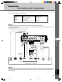
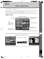
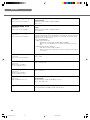
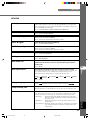
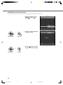
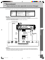
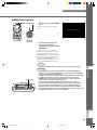
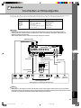
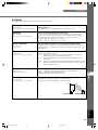
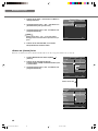
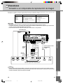
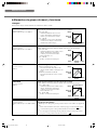
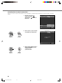
Connecting to AV components
This unit is equipped with 7 types of video input jacks for AV components. Follow the diagram to connect AV components to this unit, taking
care to use cables and adapters that match the input jacks.
Warning
• Be sure to turn off the power of this unit and the source component before attempting connection.
• Connection methods and jack names may differ depending on the component you are attempting to connect. Refer to the owner’s
manual for the component.
• Insert all plugs firmly to avoid noise or other problems.
Memo
• Be sure to connect Y/PB/PR and Y/CB/CR to the jacks with the correct signals when connecting AV components to INPUT A. Refer to
the owner’s manual of the source component for more information. You may need to make connections to HD/SYNC and VD for
RGB video signals.
D connector
cable
D-sub
monitor
cable
BNC cable for
component connection
Pin/BNC
adapters
Pin cable
Video pin cable
S-Video cable
D1—4
output
connectors
Pin jacksD-sub
Component/RGB video output connectors
Image output from AV components
BNC jacks S-Video output
jack
Video output
jack
HDMI cable (digital)
HDMI
output
connector
7 Connection
DVI cable (digital)
DVI output
connector
Input
VIDEO
S VIDEO
INPUT A
INPUT B
D4 VIDEO
HDMI
DVI
Signal type
Composite video
S-Video
Component video/RGB video
Component video/RGB video
Component video
Component video/RGB video (digital)
RGB video (digital)
Connector type
Pin jack
Mini DIN connector
BNC connector x 3-5
D-sub 15 pin
D connector
HDMI connector
DVI connector
HDMI
G/Y B/P
B
/C
B
R/P
R
/C
R
INPUT A
HD/SYNC
VD
OUT IN
REMOTE
TRIGGER OUT
S VIDEO VIDEO
INPUT B
RGB/YP
B
P
R
/YC
B
C
R
RS-232C
D4 VIDEO
DVI
G
/
YR
/
P
R
/
C
R
B
/
P
B
/
C
B
11_DPX-1300_E.p65 9/20/05, 5:07 PM15

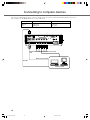
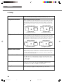
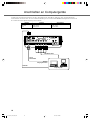
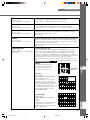
16
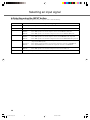
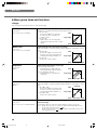
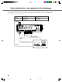
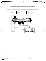
You can use the following three methods to connect to computer devices. Be sure to use cables with jacks that match the connectors and
jacks you wish to use. The HDMI terminal does not support PC signals.
Connecting to computer devices
HDMIDVI
G/Y B/P
B
/C
B
R/P
R
/C
R
INPUT A
HD/SYNC
VD
OUT IN
REMOTE
TRIGGER OUT
S VIDEO VIDEO
INPUT B
RGB/YP
B
P
R
/YC
B
C
R
RS-232C
D4 VIDEO
D-Sub monitor
cable
BNC monitor cable
Monitor output terminal
Computer devices
Input
INPUT A
INPUT B
DVI
Signal type
RGB (Analog)
RGB (Analog)
RGB (Digital)
Connector type
BNC jack x 5
D-sub 15 pin
DVI connector
DVI cable
11_DPX-1300_E.p65 9/20/05, 5:07 PM16

17
Projection
8
English
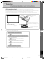
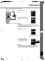
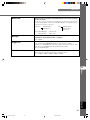
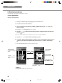
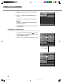
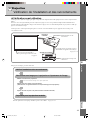
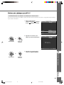
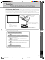
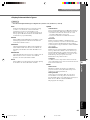
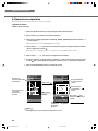
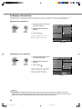
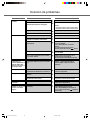
Checking installation and connections
◆ Pre-operation check
Prior to projection, adjust settings to suit the location of the main unit and screen, and the input signal you are using.
However, there is usually no need to adjust any settings if you have not changed the installation location or components since the last time
you used this unit. Check settings and connections only when the unit does not appear to project images correctly.
PHONO
DVR
STANDBY
/ON
PURE DIRECT
2CH/MULTI CH
SPEAKERS
VIDEO AUX
REC OUT/ZONE 2
INPUT MODE
SOURCE/REMOTE
DVDDTV/LD
MD/TAPE
CD-R
TUNER
CD
VIDEO AUX
VCR 2
VCR 1
SAT
CABLE
A B
STRAIGHT
EFFECT
MULTI CH
INPUT
DSP
PROGRAM
BALANCE
TONE
CONTROL
VOLUME
INPUT SELECTOR
MULTI JOG
SILENT OPTIMIZER
MIC
PHONES
OPTICAL
R
AUDIO
L
VIDEO
S VIDEO
Is the main unit power
turned on?
Main unit
Are the components connected correctly?
“Connecting to AV components”
☞ page 15 - 16
Image source component
Is the source component power
turned on?
For an explanation of detailed settings, see “Menu”. ☞ page 27 - 47
Check installation and connections
Select an image for projection and image adjustment
Projection preparations complete
Turn on the projector power.
Begin playback of the source image for adjustment.
Select a projection image.
(Select an input signal and projection image aspect.)
Adjust focus and vertical/ horizontal positioning.
8 Projection
Prior to projection, check that the main unit and screen are correctly installed, and that source components are connected correctly.
To project images, carry out the following procedure.
Is the screen installed correctly?
“Setting up the DPX-1300”
☞ page 12
12_DPX-1300_E.p65 9/20/05, 5:07 PM17

18
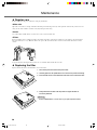
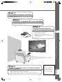
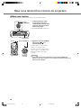
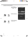
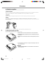
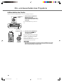
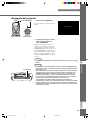
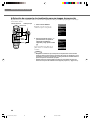
◆ Turning the power on
Always remove the lens cap before operating the main unit.
1. Insert the supplied power cable
firmly into the AC inlet at the rear
of the main unit, then insert the
plug into an AC outlet.
The STANDBY/ON indicator lights red.
2. Press the STANDBY/ON button
(the
button on the remote
control).
The indicator blinks green and the lamp
lights up in preparation for projection. After
approximately 35 seconds, the indicator
changes from blinking to steady green,
indicating that the unit is ready to project.
Warning
• Do not remove the power cable while the STANDBY/ON indicator is blinking green or
lit steady green. This could damage the lamp or reduce lamp life.
HDMIDVI
G/Y B/P
B
/C
B
R/P
R
/C
R
INPUT A
HD/SYNC
VD
OUT IN
REMOTE
TRIGGER OUT
S-VIDEO VIDEO
INPUT B
RGB/YP
B
P
R
/YC
B
C
R
RS-232C
D4 VIDEO
STANDBY
/
ON
SETTING
LAMP COVER TEMP FAN
PATTERN
ESCAPE
MENU
INPUT
ASPECT
STANDBY/ON
indicator
AC inlet
INPUT
MENU
PATTIRIS
AUTO
SETTING
ASPECT
ZOOM FOCUSV. POS
ESCAPE
STANDBY
/
ON
SETTING
LAMP COVER TEMP FAN
PATTERN
ESCAPE
MENU
INPUT
ASPECT
Remote Control Main unit
button STANDBY/ON button
Turning the projector power on
12_DPX-1300_E.p65 9/20/05, 5:07 PM18
Sidan laddas ...
Sidan laddas ...
Sidan laddas ...
Sidan laddas ...
Sidan laddas ...
Sidan laddas ...
Sidan laddas ...
Sidan laddas ...
Sidan laddas ...
Sidan laddas ...
Sidan laddas ...
Sidan laddas ...
Sidan laddas ...
Sidan laddas ...
Sidan laddas ...
Sidan laddas ...
Sidan laddas ...
Sidan laddas ...
Sidan laddas ...
Sidan laddas ...
Sidan laddas ...
Sidan laddas ...
Sidan laddas ...
Sidan laddas ...
Sidan laddas ...
Sidan laddas ...
Sidan laddas ...
Sidan laddas ...
Sidan laddas ...
Sidan laddas ...
Sidan laddas ...
Sidan laddas ...
Sidan laddas ...
Sidan laddas ...
Sidan laddas ...
Sidan laddas ...
Sidan laddas ...
Sidan laddas ...
Sidan laddas ...
Sidan laddas ...
Sidan laddas ...
Sidan laddas ...
Sidan laddas ...
Sidan laddas ...
Sidan laddas ...
Sidan laddas ...
Sidan laddas ...
Sidan laddas ...
Sidan laddas ...
Sidan laddas ...
Sidan laddas ...
Sidan laddas ...
Sidan laddas ...
Sidan laddas ...
Sidan laddas ...
Sidan laddas ...
Sidan laddas ...
Sidan laddas ...
Sidan laddas ...
Sidan laddas ...
Sidan laddas ...
Sidan laddas ...
Sidan laddas ...
Sidan laddas ...
Sidan laddas ...
Sidan laddas ...
Sidan laddas ...
Sidan laddas ...
Sidan laddas ...
Sidan laddas ...
Sidan laddas ...
Sidan laddas ...
Sidan laddas ...
Sidan laddas ...
Sidan laddas ...
Sidan laddas ...
Sidan laddas ...
Sidan laddas ...
Sidan laddas ...
Sidan laddas ...
Sidan laddas ...
Sidan laddas ...
Sidan laddas ...
Sidan laddas ...
Sidan laddas ...
Sidan laddas ...
Sidan laddas ...
Sidan laddas ...
Sidan laddas ...
Sidan laddas ...
Sidan laddas ...
Sidan laddas ...
Sidan laddas ...
Sidan laddas ...
Sidan laddas ...
Sidan laddas ...
Sidan laddas ...
Sidan laddas ...
Sidan laddas ...
Sidan laddas ...
Sidan laddas ...
Sidan laddas ...
Sidan laddas ...
Sidan laddas ...
Sidan laddas ...
Sidan laddas ...
Sidan laddas ...
Sidan laddas ...
Sidan laddas ...
Sidan laddas ...
Sidan laddas ...
Sidan laddas ...
Sidan laddas ...
Sidan laddas ...
Sidan laddas ...
Sidan laddas ...
Sidan laddas ...
Sidan laddas ...
Sidan laddas ...
Sidan laddas ...
Sidan laddas ...
Sidan laddas ...
Sidan laddas ...
Sidan laddas ...
Sidan laddas ...
Sidan laddas ...
Sidan laddas ...
Sidan laddas ...
Sidan laddas ...
Sidan laddas ...
Sidan laddas ...
Sidan laddas ...
Sidan laddas ...
Sidan laddas ...
Sidan laddas ...
Sidan laddas ...
Sidan laddas ...
Sidan laddas ...
Sidan laddas ...
Sidan laddas ...
Sidan laddas ...
Sidan laddas ...
Sidan laddas ...
Sidan laddas ...
Sidan laddas ...
Sidan laddas ...
Sidan laddas ...
Sidan laddas ...
Sidan laddas ...
Sidan laddas ...
Sidan laddas ...
Sidan laddas ...
Sidan laddas ...
Sidan laddas ...
Sidan laddas ...
Sidan laddas ...
Sidan laddas ...
Sidan laddas ...
Sidan laddas ...
Sidan laddas ...
Sidan laddas ...
Sidan laddas ...
Sidan laddas ...
Sidan laddas ...
Sidan laddas ...
Sidan laddas ...
Sidan laddas ...
Sidan laddas ...
Sidan laddas ...
Sidan laddas ...
Sidan laddas ...
Sidan laddas ...
Sidan laddas ...
Sidan laddas ...
Sidan laddas ...
Sidan laddas ...
Sidan laddas ...
Sidan laddas ...
Sidan laddas ...
Sidan laddas ...
Sidan laddas ...
Sidan laddas ...
Sidan laddas ...
Sidan laddas ...
Sidan laddas ...
Sidan laddas ...
Sidan laddas ...
Sidan laddas ...
Sidan laddas ...
Sidan laddas ...
Sidan laddas ...
Sidan laddas ...
Sidan laddas ...
Sidan laddas ...
Sidan laddas ...
Sidan laddas ...
Sidan laddas ...
Sidan laddas ...
Sidan laddas ...
Sidan laddas ...
Sidan laddas ...
Sidan laddas ...
Sidan laddas ...
Sidan laddas ...
Sidan laddas ...
Sidan laddas ...
Sidan laddas ...
Sidan laddas ...
Sidan laddas ...
Sidan laddas ...
Sidan laddas ...
Sidan laddas ...
Sidan laddas ...
Sidan laddas ...
Sidan laddas ...
Sidan laddas ...
Sidan laddas ...
Sidan laddas ...
Sidan laddas ...
Sidan laddas ...
Sidan laddas ...
Sidan laddas ...
Sidan laddas ...
Sidan laddas ...
Sidan laddas ...
Sidan laddas ...
Sidan laddas ...
Sidan laddas ...
Sidan laddas ...
Sidan laddas ...
Sidan laddas ...
Sidan laddas ...
Sidan laddas ...
Sidan laddas ...
Sidan laddas ...
Sidan laddas ...
Sidan laddas ...
Sidan laddas ...
Sidan laddas ...
Sidan laddas ...
Sidan laddas ...
Sidan laddas ...
Sidan laddas ...
Sidan laddas ...
Sidan laddas ...
Sidan laddas ...
-
 1
1
-
 2
2
-
 3
3
-
 4
4
-
 5
5
-
 6
6
-
 7
7
-
 8
8
-
 9
9
-
 10
10
-
 11
11
-
 12
12
-
 13
13
-
 14
14
-
 15
15
-
 16
16
-
 17
17
-
 18
18
-
 19
19
-
 20
20
-
 21
21
-
 22
22
-
 23
23
-
 24
24
-
 25
25
-
 26
26
-
 27
27
-
 28
28
-
 29
29
-
 30
30
-
 31
31
-
 32
32
-
 33
33
-
 34
34
-
 35
35
-
 36
36
-
 37
37
-
 38
38
-
 39
39
-
 40
40
-
 41
41
-
 42
42
-
 43
43
-
 44
44
-
 45
45
-
 46
46
-
 47
47
-
 48
48
-
 49
49
-
 50
50
-
 51
51
-
 52
52
-
 53
53
-
 54
54
-
 55
55
-
 56
56
-
 57
57
-
 58
58
-
 59
59
-
 60
60
-
 61
61
-
 62
62
-
 63
63
-
 64
64
-
 65
65
-
 66
66
-
 67
67
-
 68
68
-
 69
69
-
 70
70
-
 71
71
-
 72
72
-
 73
73
-
 74
74
-
 75
75
-
 76
76
-
 77
77
-
 78
78
-
 79
79
-
 80
80
-
 81
81
-
 82
82
-
 83
83
-
 84
84
-
 85
85
-
 86
86
-
 87
87
-
 88
88
-
 89
89
-
 90
90
-
 91
91
-
 92
92
-
 93
93
-
 94
94
-
 95
95
-
 96
96
-
 97
97
-
 98
98
-
 99
99
-
 100
100
-
 101
101
-
 102
102
-
 103
103
-
 104
104
-
 105
105
-
 106
106
-
 107
107
-
 108
108
-
 109
109
-
 110
110
-
 111
111
-
 112
112
-
 113
113
-
 114
114
-
 115
115
-
 116
116
-
 117
117
-
 118
118
-
 119
119
-
 120
120
-
 121
121
-
 122
122
-
 123
123
-
 124
124
-
 125
125
-
 126
126
-
 127
127
-
 128
128
-
 129
129
-
 130
130
-
 131
131
-
 132
132
-
 133
133
-
 134
134
-
 135
135
-
 136
136
-
 137
137
-
 138
138
-
 139
139
-
 140
140
-
 141
141
-
 142
142
-
 143
143
-
 144
144
-
 145
145
-
 146
146
-
 147
147
-
 148
148
-
 149
149
-
 150
150
-
 151
151
-
 152
152
-
 153
153
-
 154
154
-
 155
155
-
 156
156
-
 157
157
-
 158
158
-
 159
159
-
 160
160
-
 161
161
-
 162
162
-
 163
163
-
 164
164
-
 165
165
-
 166
166
-
 167
167
-
 168
168
-
 169
169
-
 170
170
-
 171
171
-
 172
172
-
 173
173
-
 174
174
-
 175
175
-
 176
176
-
 177
177
-
 178
178
-
 179
179
-
 180
180
-
 181
181
-
 182
182
-
 183
183
-
 184
184
-
 185
185
-
 186
186
-
 187
187
-
 188
188
-
 189
189
-
 190
190
-
 191
191
-
 192
192
-
 193
193
-
 194
194
-
 195
195
-
 196
196
-
 197
197
-
 198
198
-
 199
199
-
 200
200
-
 201
201
-
 202
202
-
 203
203
-
 204
204
-
 205
205
-
 206
206
-
 207
207
-
 208
208
-
 209
209
-
 210
210
-
 211
211
-
 212
212
-
 213
213
-
 214
214
-
 215
215
-
 216
216
-
 217
217
-
 218
218
-
 219
219
-
 220
220
-
 221
221
-
 222
222
-
 223
223
-
 224
224
-
 225
225
-
 226
226
-
 227
227
-
 228
228
-
 229
229
-
 230
230
-
 231
231
-
 232
232
-
 233
233
-
 234
234
-
 235
235
-
 236
236
-
 237
237
-
 238
238
-
 239
239
-
 240
240
-
 241
241
-
 242
242
-
 243
243
-
 244
244
-
 245
245
-
 246
246
-
 247
247
-
 248
248
-
 249
249
-
 250
250
-
 251
251
-
 252
252
-
 253
253
-
 254
254
-
 255
255
-
 256
256
-
 257
257
-
 258
258
-
 259
259
-
 260
260
-
 261
261
-
 262
262
-
 263
263
-
 264
264
-
 265
265
-
 266
266


Yamaha DPX-1300 Bruksanvisning
- Kategori
- Dataprojektorer
- Typ
- Bruksanvisning
på andra språk
- italiano: Yamaha DPX-1300 Manuale del proprietario
- español: Yamaha DPX-1300 El manual del propietario
- Deutsch: Yamaha DPX-1300 Bedienungsanleitung
- français: Yamaha DPX-1300 Le manuel du propriétaire
- Türkçe: Yamaha DPX-1300 El kitabı
- English: Yamaha DPX-1300 Owner's manual
- dansk: Yamaha DPX-1300 Brugervejledning
- suomi: Yamaha DPX-1300 Omistajan opas
- Nederlands: Yamaha DPX-1300 de handleiding
- română: Yamaha DPX-1300 Manualul proprietarului
Relaterade papper
-
Yamaha DPX-1100 Bruksanvisning
-
Yamaha DPX-1200 Bruksanvisning
-
-
-
-
-
-
-
-
Andra dokument
-
Philips SWV4422S/10 Användarmanual
-
AIPTEK PocketCinema V100 Användarmanual
-
AIPTEK V10 Bruksanvisning
-
Samsung SP-LSP3BLAXZA Användarmanual
-
Samsung Freestyle Användarmanual
-
Pioneer HDMI TM (PDP-504/434HDE) Bruksanvisning
-
BenQ ScreenBar Halo Användarmanual
-
-
BenQ MX819ST Snabbstartsguide
-
BenQ MX631ST Snabbstartsguide