
ASSALUB AB, Box 240, S-597 26 ÅTVIDABERG, SWEDEN
Tel. +46-(0)120-358 40, Fax +46-(0)120-152 11, E-Mail [email protected]
www.assalub.se
I26112-SE-14.10
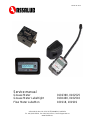
Service manual
Grease Meter 0102390, 0102525
Grease Meter LubeRight 0102400, 0102510
Flow Meter LubeMon 101918, 101919

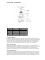
SPARE PARTS RESERVDELAR
Art. No. Designation Benämning
0122378 Cover Lock
0122380 Pin Pinne
901444 Oval gear Ovalkugghjul
906960 Magnet Magnet
906961 Screw 6x25 Skruv 6x25
906963 O-ring 23.53x1.78 O-ring 23,53x1,78
F1533 Pin 4x10 Pin 4x10
Principle of operation
The grease meter has two oval gear wheels which are made rotating by the grease flow.
Inside the left wheel two magnets are mounted. Right above the left wheel in the aluminium
housing a reed switch is mounted. Each time the two magnets are in line with the reed
switch, it closes. The volume required for one pulse is approx. 0.7 cm³. The electronics
processes the pulses and presents the volume in the chosen unit on the display.
Service electronic part
Always check the batteries condition before any further steps. The grease meter has a
membrane panel which is sealed with silicone when mounted, to achieve IP 65. To access
the PCB with reed switch and display the membrane panel has to be removed and
replaced. We recommend the unit is sent to manufacturer for repair of electronic failures.
Service mechanical part
If a meter functions electronically but do not count despite grease flow, the cause can be
contaminations at the gear wheels which prevent them from rotating. There can still be a
grease flow through the meter despite the wheels are stuck by contaminations. Due to the
high pressure of the grease, the gear wheels will be compressed and allow grease flow.

Disassembly
Unscrew the four screws to the cover.
Gently remove the cover. The cover is guided by two pins.
There is an O-ring in a groove in the cover. Check the condition of the O-ring.
If the meter has been exposed to higher pressures than allowed the O-ring can be
damaged. In that case the housing can also be damaged (lost its original form), and the
meter will in that case not have the stated accuracy.
To determine the state of the meter it should be calibrated according to the user’s manual.
The calculated calibration factor should never exceed 750.
Remove the two pins which the oval gear wheels rotate around.
Remove the two oval gear wheels.
Important:
Note how the oval gear wheels are placed. The wheel containing the two magnets shall be
mounted to the left, to the same direction as the battery cover.
The magnets shall be mounted downwards facing the electronics.
Check for contaminations, clean with solvent.
Check the oval gear wheels condition, if any visible damage replace.
Remount the pins and oval gear wheels in the housing.
Carefully rotate one wheel with a small screwdriver. The other wheel will follow easily if
mounted correctly.
Mount the O-ring in the groove of the cover.
(If the O-ring is replaced, only use original spare part, the O-ring is not standard type.)
Mount the two guiding pins in housing. Remount the cover.
Mount the four screws to the cover. The screws shall be tightened crosswise first to 7 Nm,
then to 14 Nm.
Funktionsbeskrivning
Fettmätaren har två ovalkugghjul som roterar av fettflödet. I det vänstra ovalkugghjulet är
två magneter monterade. Ovanför det vänstra kugghjulet finns ett tungelement monterat i
aluminiumhuset. Tungelementet sluter då magneterna står i linje med det.
Erforderlig volym per puls är ca 0,7 cm³. Pulserna behandlas av elektroniken, och flödet
presenteras på display i vald enhet.
Service elektronikdel
Kontrollera alltid först att batterierna är i bra skick. Fettmätarens membrantangentbord är
tätat med silikon vid monteringen för att uppnå IP 65. För att komma åt kretskort med
display och tungelement måste membrantangentbordet tas bort och bytas ut.
Vi rekommenderar därför att fettmätaren skickas till fabrik för reparation av elektronikfel.
Service mekanisk del
Om en fettmätare fungerar elektroniskt, men ej räknar trots fettflöde, kan detta bero på att
föroreningar fastnat vid ovalkugghjulen och hindrar dem från att rotera. Fett kan flyta genom
fettmätaren trots att ovalkugghjulen hindras från att rotera då det höga trycket från fettet
komprimerar ovalkugghjulen
.

Isärtagning
Lossa de fyra skruvarna som håller fast locket på fettmätaren.
Ta försiktigt bort locket. Locket sitter monterat på två styrpinnar.
En O-ring är monterad i ett spår i locket. Kontrollera att O-ringen är oskadad.
Om en fettmätare utsatts för tryck högre än tillåtet kan O-ringen ha skadats.
I så fall kan även huset ha skadats och mist sin form, vilket leder till att fettmätaren inte
längre har uppgiven noggrannhet.
För att avgöra fettmätarens skick skall den kalibreras enligt instruktionerna i
instruktionsboken.
Kalibreringsfaktorn skall aldrig överstiga 750.
Lossa de två pinnarna hjulen roterar runt.
Ta bort de två ovalkugghjulen.
Viktigt:
Observera hur ovalkugghjulen är monterade. Ovalkugghjulet med de två magneterna, skall
sitta till vänster, dvs åt samma håll som batterilocket. Magneterna skall vara monterade
nedåt mot elektroniken.
Kontrollera att det ej finns föroreningar, rengör.
Kontrollera ovalkugghjulens skick, vid skador skall de bytas ut.
Återmontera pinnarna ovalkugghjulen roterar runt, samt ovalkugghjulen i huset.
Rotera försiktigt det ena ovalkugghjulet med en liten skruvmejsel. Det andra ovalkugghjulet
följer lätt med om det monterats rätt.
Montera O-ringen i spåret i locket.
(Om O-ringen ersatts, bör endast originalreservdelar användas, är ej standardtyp.)
Montera de två styrpinnarna i huset. Montera locket.
Skruva fast de fyra skruvarna till locket. Skruvarna skall momentdras korsvis, först till 7 Nm,
slutligen till 14 Nm.
-
 1
1
-
 2
2
-
 3
3
-
 4
4


på andra språk
- English: ASSALUB 0102390 User manual
Andra dokument
-
Woods BATWING BW20.50QE Användarmanual
-
Sioux Tools SAG10AX18 Bruksanvisningar
-
-
-
Woods Batwing BW10.70QE Användarmanual
-
Murray 629904X54A Bruksanvisning
-
-
Simplicity STIGA ROYAL LARGE FRAME SNOWTHROWERS Användarmanual