Dell OptiPlex 320 Snabbstartsguide
- Kategori
- Mixer / matberedare tillbehör
- Typ
- Snabbstartsguide

www.dell.com | support.dell.com
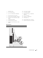
Dell™ OptiPlex™ 320
Quick Reference Guide
Models DCSM, DCNE

Notes, Notices, and Cautions
NOTE: A NOTE indicates important information that helps you make better use of your computer.
NOTICE: A NOTICE indicates either potential damage to hardware or loss of data and tells you how to avoid the
problem.
CAUTION: A CAUTION indicates a potential for property damage, personal injury, or death.
If you purchased a Dell™ n Series computer, any references in this document to Microsoft
®
Windows
®
operating systems are not applicable.
____________________
Information in this document is subject to change without notice.
© 2006 Dell Inc. All rights reserved.
Reproduction in any manner whatsoever without the written permission of Dell Inc. is strictly forbidden.
Trademarks used in this text: Dell, OptiPlex, and the DELL logo are trademarks of Dell Inc.; Microsoft and Windows are registered trademarks
of Microsoft Corporation; Intel and Pentium are registered trademarks of Intel Corporation.
Other trademarks and trade names may be used in this document to refer to either the entities claiming the marks and names or their products.
Dell Inc. disclaims any proprietary interest in trademarks and trade names other than its own.
Models DCSM, DCNE
September 2006 P/N GK385 Rev. A01

Contents 3
Contents
Finding Information . . . . . . . . . . . . . . . . . . . . . . . . . . . . . . . . 5
Setting Up Your Computer
. . . . . . . . . . . . . . . . . . . . . . . . . . . . . 8
System Views
. . . . . . . . . . . . . . . . . . . . . . . . . . . . . . . . . . 11
Mini Tower Computer — Front View
. . . . . . . . . . . . . . . . . . . . 11
Mini Tower Computer — Back View
. . . . . . . . . . . . . . . . . . . . 13
Mini Tower Computer — Back-Panel Connectors
. . . . . . . . . . . . . 14
Desktop Computer — Front View
. . . . . . . . . . . . . . . . . . . . . . 16
Desktop Computer — Back View
. . . . . . . . . . . . . . . . . . . . . . 17
Desktop Computer — Back-Panel Connectors
. . . . . . . . . . . . . . 18
Removing the Computer Cover
. . . . . . . . . . . . . . . . . . . . . . . . . . 20
Before You Begin
. . . . . . . . . . . . . . . . . . . . . . . . . . . . . . 20
Mini Tower Computer
. . . . . . . . . . . . . . . . . . . . . . . . . . . . 21
Desktop Computer
. . . . . . . . . . . . . . . . . . . . . . . . . . . . . 23
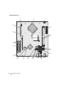
Inside Your Computer
. . . . . . . . . . . . . . . . . . . . . . . . . . . . . . 24
Mini Tower Computer
. . . . . . . . . . . . . . . . . . . . . . . . . . . . 24
Desktop Computer
. . . . . . . . . . . . . . . . . . . . . . . . . . . . . 27
Solving Problems
. . . . . . . . . . . . . . . . . . . . . . . . . . . . . . . . 30
Dell Diagnostics
. . . . . . . . . . . . . . . . . . . . . . . . . . . . . . . 30
System Lights
. . . . . . . . . . . . . . . . . . . . . . . . . . . . . . . . 33
Diagnostic Lights
. . . . . . . . . . . . . . . . . . . . . . . . . . . . . . . . . 34
Beep Codes
. . . . . . . . . . . . . . . . . . . . . . . . . . . . . . . . . 37
Resolving Software and Hardware Incompatibilities
. . . . . . . . . . . 38
Using Microsoft Windows XP System Restore
. . . . . . . . . . . . . . . 38
Reinstalling Microsoft Windows XP
. . . . . . . . . . . . . . . . . . . . 39
Using the Drivers and Utilities CD
. . . . . . . . . . . . . . . . . . . . . . . . 42
Index . . . . . . . . . . . . . . . . . . . . . . . . . . . . . . . . . . . . . . . . . 43

4 Contents

Quick Reference Guide 5
Finding Information
NOTE: Some features or media may be optional and may not ship with your computer. Some features or media may
not be available in certain countries.
NOTE: Additional information may ship with your computer.
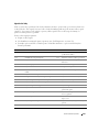
What Are You Looking For? Find It Here
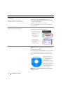
• A diagnostic program for my computer
• Drivers for my computer
• My computer documentation
• My device documentation
• Desktop System Software (DSS)
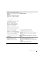
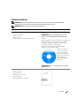
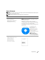
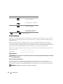
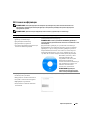
Drivers and Utilities CD (also known as ResourceCD)
NOTE: The Drivers and Utilities CD may be optional and may
not ship with your computer.
Documentation and drivers are already installed on your
computer. You can use the CD to reinstall drivers (see
"Reinstalling Drivers and Utilities" in your online User’s
Guide), to run the Dell Diagnostics (see "Dell Diagnostics"
on page 30), or to access your documentation.
Readme files may be
included on your CD to
provide the most current
updates about technical
changes to your computer
or advanced technical-
reference material for
technicians or experienced
users.
NOTE: Drivers and documentation updates can be found at
support.dell.com.
• Warranty information
• Terms and Conditions (U.S. only)
• Safety instructions
• Regulatory information
• Ergonomics information
• End User License Agreement
Dell™ Product Information Guide

6 Quick Reference Guide
• How to remove and replace parts
• Specifications
• How to configure system settings
• How to troubleshoot and solve problems
Dell™ OptiPlex™ User’s Guide
Microsoft Windows XP Help and Support Center
1
Click
Start
→
Help and Support
→
Dell User and System
Guides
→
System Guides
.
2
Click the
User’s Guide
for your computer.
The User’s Guide is also available on the optional Drivers
and Utilities CD.
• Service Tag and Express Service Code
• Microsoft Windows License Label
Service Tag and Microsoft
®
Windows
®
License
These labels are located on your computer.
• Use the Service Tag to
identify your computer
when you use
support.dell.com
or
contact support.
• Enter the Express
Service Code to direct
your call when
contacting support.
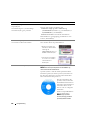
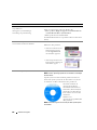
• How to reinstall my operating system
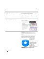
Operating System CD
NOTE: The Operating System CD may be optional and may
not ship with your computer.
The operating system is already installed on your computer.
To reinstall your operating system, use the Operating
System CD. See "Reinstalling Microsoft Windows XP" on
page 39.
After you reinstall your
operating system, you can
use the optional Drivers
and Utilities CD
(ResourceCD) to reinstall
drivers for the devices that
came with your computer.
Your operating system
product key label is located
on your computer.
NOTE: The color of your CD varies based on the operating
system you ordered.
What Are You Looking For? Find It Here

Quick Reference Guide 7
• Solutions — Troubleshooting hints and tips, articles from
technicians, frequently asked questions, and online
courses
• Community — Online discussion with other Dell
customers
• Upgrades — Upgrade information for components, such
as memory, the hard drive, and the operating system
• Customer Care — Contact information, service call and
order status, warranty, and repair information
• Service and support — Service call status and support
history, service contract, online discussions with technical
support
• Reference — Computer documentation, details on my
computer configuration, product specifications, and white
papers
• Downloads — Certified drivers, patches, and software
updates
• Desktop System Software (DSS) — If you reinstall the
operating system for your computer, you should also
reinstall the DSS utility. DSS provides critical updates for
your operating system and support for Dell™ 3.5-inch
USB floppy drives, Intel
®
processors, optical drives, and
USB devices. DSS is necessary for correct operation of
your Dell computer. The software automatically detects
your computer and operating system and installs the
updates appropriate for your configuration.
Dell Support Website — support.dell.com
NOTE: Select your region or business segment to view the
appropriate support site.
To download Desktop System Software:
1
Go to
support.dell.com
, select your region or business
segment, and enter your Service Tag.
2
Select
Drivers & Downloads
and click
Go
.
3
Click your operating system and search for the keyword
Desktop System Software
.
NOTE: The support.dell.com user interface may vary
dependent upon your selections.
• How to use Windows XP
• How to work with programs and files
• How to personalize my desktop
Windows Help and Support Center
1
Click
Start
→
Help and Support
.
2
Type a word or phrase that describes your problem and
click the arrow icon.
3
Click the topic that describes your problem.
4
Follow the instructions on the screen.
What Are You Looking For? Find It Here

8 Quick Reference Guide
Setting Up Your Computer
CAUTION: Before performing any of the procedures in this section, follow the safety instructions in Product
Information Guide.
NOTICE: If your computer has an expansion card installed (such as a modem card), connect the appropriate cable
to the card, not to the connector on the back panel.
NOTICE: To help allow the computer to maintain proper operating temperature, ensure that you do not place the
computer too close to a wall or other storage compartment that might prevent air circulation around the chassis.
NOTE: Before you install any devices or software that did not ship with your computer, read the documentation
that came with the device or software, or contact the vendor to verify that the device or software is compatible
with your computer and operating system.
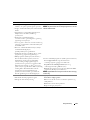
You must complete all the steps to properly set up your computer. See the appropriate figures that follow
the instructions.
NOTICE: Do not attempt to operate a PS/2 mouse and a USB mouse simultaneously.
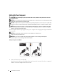
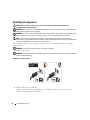
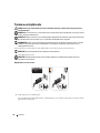
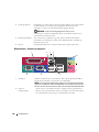
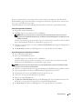
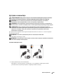
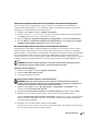
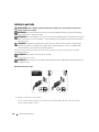
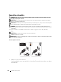
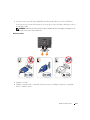
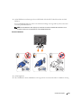
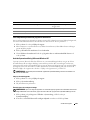
1
Connect the keyboard and mouse.
NOTICE: Do not connect a modem cable to the network adapter connector. Voltage from telephone
communications can cause damage to the network adapter.
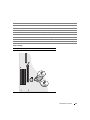
Set Up Your Keyboard and Mouse
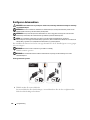
2
Connect the modem or network cable.
Insert the network cable, not the telephone line, into the network connector. If you have an optional
modem, connect the telephone line to the modem.

Quick Reference Guide 9
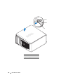
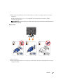
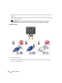
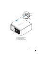
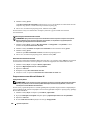
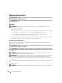
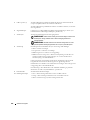
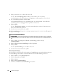
3
Connect the monitor using
either
the white DVI cable
or
the blue VGA cable (
do not
connect both
cables).
Align and gently insert the monitor cable to avoid bending connector pins. Tighten the thumbscrews
on the cable connectors.
NOTE: Some monitors have the video connector underneath the back of the screen. See the documentation
that came with your monitor for its connector locations.
Set Up Your Monitor
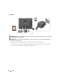
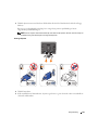
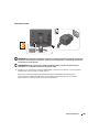
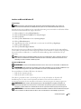
4
Connect the speakers.
5
Connect power cables to the computer, monitor, and devices and connect the other ends of the power
cables to electrical outlets.

10 Quick Reference Guide
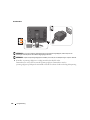
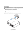
Power Connections
NOTICE: To avoid damaging a computer with a manual voltage-selection switch, set the switch for the voltage that
most closely matches the AC power available in your location.
NOTICE: In Japan, the voltage selection switch must be set to the 115-V position even though the AC power
available in Japan is 100 V.
6
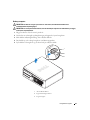
Verify that the voltage selection switch is set correctly for your location.
Your computer has a manual voltage-selection switch. Computers with a voltage selection switch on
the back panel must be manually set to operate at the correct operating voltage.

Quick Reference Guide 11
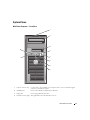
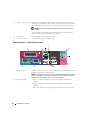
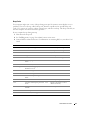
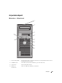
System Views
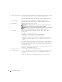
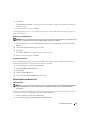
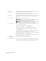
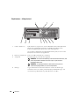
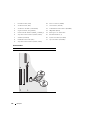
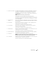
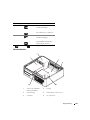
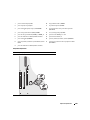
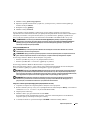
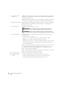
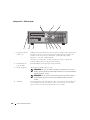
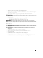
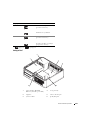
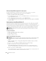
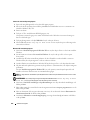
Mini Tower Computer — Front View
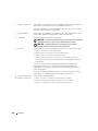
1 location of Service Tag Use the Service Tag to identify your computer when you access the Dell Support
website or call technical support.
2 CD/DVD drive Insert a CD or DVD (if supported) into this drive.
3 floppy drive Insert a floppy disk into this drive.
4 hard-drive activity light This light flickers when the hard drive is in use.
4
9
7
8
3
2
6
5
1
10

12 Quick Reference Guide
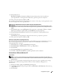
5 USB 2.0 connectors (2) Use the USB connectors on the front of the computer for devices that you connect
occasionally, such as joysticks or cameras, or for bootable USB devices.
It is recommended that you use the USB connectors on the back of the computer
for devices that typically remain connected, such as printers and keyboards.
6 diagnostic lights Use the lights to help you troubleshoot a computer problem based on the
diagnostic code (for more information, see "Diagnostic Lights" on page 34).
7 power button Press this button to turn on the computer.
NOTICE: To avoid losing data, do not turn off the computer by pressing the
power button. Instead, perform an operating system shutdown.
NOTICE: If your operating system has ACPI enabled, when you press the power
button the computer will perform an operating system shutdown.
8 power light The power light illuminates and blinks or remains solid to indicate different
operating states:
• No light — The computer is turned off.
• Steady green — The computer is in a normal operating state.
• Blinking green — The computer is in a power-saving mode.
• Blinking or solid amber — The computer is receiving electrical power, but an
internal power problem might exist. See "Power Problems" in your online
User’s
Guide
.
To exit from a power-saving mode, press the power button or use the keyboard or
the mouse if it is configured as a wake device in the Windows Device Manager. For
more information about sleep modes and exiting from a power-saving mode, see
your online User’s Guide.
For a description of light codes that can help you troubleshoot problems with your
computer, see "System Lights" on page 33.
9 headphone connector Use the headphone connector to attach headphones.
10 link integrity light
• Green — A good connection exists between a 10-Mbps network and the computer.
• Orange — A good connection exists between a 100-Mbps network and the
computer.
• Off — The computer is not detecting a physical connection to the network.

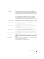
Quick Reference Guide 13
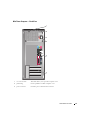
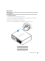
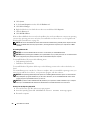
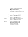
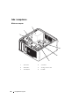
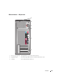
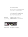
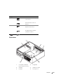
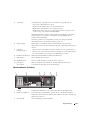
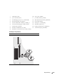
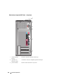
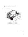
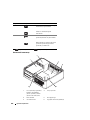
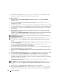
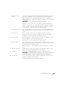
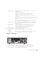
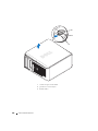
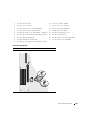
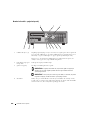
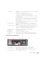
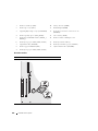
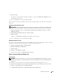
Mini Tower Computer — Back View
1
cover release latch
This latch allows you to open the computer cover.
2
padlock ring
Insert a padlock to lock the computer cover.
3 power connector Insert the power cable into this connector.
4
3
5
6
2
1

14 Quick Reference Guide
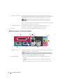
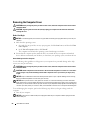
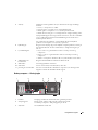
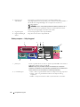
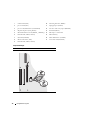
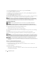
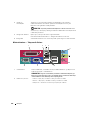
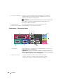
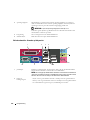
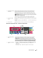
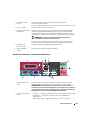
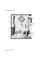
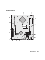
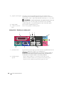
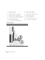
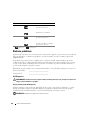
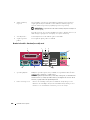
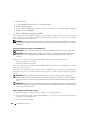
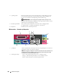
Mini Tower Computer — Back-Panel Connectors
4 voltage selection switch Your computer is equipped with a manual voltage-selection switch. To avoid
damaging a computer with a manual voltage-selection switch, set the switch for the
voltage that most closely matches the AC power available in your location.
NOTICE: In Japan the voltage-selection switch must be set to the 115-V
position.
Also, ensure that your monitor and attached devices are electrically rated to operate
with the AC power available in your location.
5 back-panel connectors Plug serial, USB, and other devices into the appropriate connector.
See "Mini Tower Computer — Back-Panel Connectors" on page 14.
6 card slots Access connectors for any installed PCI and PCI Express cards.
1
parallel connector
Connect a parallel device, such as a printer, to the parallel connector. If you have a
USB printer, plug it into a USB connector.
NOTE: The integrated parallel connector is automatically disabled if the computer
detects an installed card containing a parallel connector configured to the same
address. For more information, see your online User’s Guide.
2
link integrity light • Green — A good connection exists between a 10-Mbps network and the
computer.
• Orange — A good connection exists between a 100-Mbps network and the
computer.
• Off — The computer is not detecting a physical connection to the network.
13
10 9 8
5
6
7
24

Quick Reference Guide 15
3
network adapter
connector
To attach your computer to a network or broadband device, connect one end of a
network cable to a network jack or your network or broadband device. Connect the
other end of the network cable to the network adapter connector on the back
panel of your computer. A click indicates that the network cable has been securely
attached.
NOTE: Do not plug a telephone cable into the network connector.
On computers with a network adapter card, use the connector on the card.
It is recommended that you use Category 5 wiring and connectors for your
network. If you must use Category 3 wiring, force the network speed to 10 Mbps
to ensure reliable operation.
4
network activity light
This light flashes yellow when the computer is transmitting or receiving network
data. A high volume of network traffic may make this light appear to be in a steady
"on" state.
5
line-in connector
Use the blue line-in connector to attach a record/playback device such as a
cassette player, CD player, or VCR.
On computers with a sound card, use the connector on the card.
6
line-out connector
Use the green line-out connector to attach headphones and most speakers with
integrated amplifiers.
On computers with a sound card, use the connector on the card.
7
microphone connector
Use the pink microphone connector to attach a personal computer microphone
for voice or musical input into a sound or telephony program.
On computers with a sound card, the microphone connector is on the card.
8
USB 2.0 connectors (4)
Use the back USB connectors for devices that typically remain connected, such as
printers and keyboards.
9
video connector
Plug the cable from your VGA-compatible monitor into the blue connector.
NOTE: If you purchased an optional graphics card, this connector will be covered by
a cap. Connect your monitor to the connector on the graphics card. Do not remove
the cap.
10
serial connector
Connect a serial device, such as a handheld device, to the serial port. The default
designation is COM1 for serial connector 1.
For more information, see your online User’s Guide.

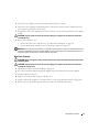
16 Quick Reference Guide
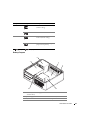
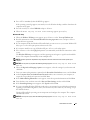
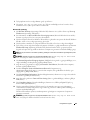
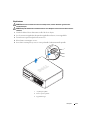
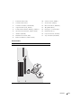
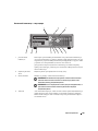
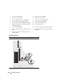
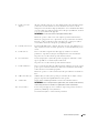
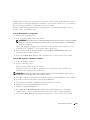
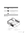
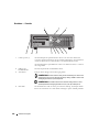
Desktop Computer — Front View
1 USB 2.0 connectors (2) Use the USB connectors on the front of the computer for devices that you
connect occasionally, such as joysticks or cameras, or for bootable USB devices
(see your online User’s Guide for more information about booting to a USB
device).
It is recommended that you use the USB connectors on the back panel for devices
that typically remain connected, such as printers and keyboards.
2 hard-drive activity light This light flickers when the hard drive is being accessed.
3 power button Press this button to turn on the computer.
NOTICE: To avoid losing data, do not turn off the computer by pressing the
power button for 6 seconds or longer. Instead, perform an operating system
shutdown.
NOTICE: If your operating system has ACPI enabled, when you press the
power button the computer will perform an operating system shutdown.
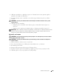
4 Dell badge This badge can be rotated to match the orientation of your computer. To rotate
the badge, place your fingers around the outside of the badge, press firmly, and
turn the badge. You can also rotate the badge using the slot provided near the
bottom of the badge.
89
3
5
1
4610
2
11
7

Quick Reference Guide 17
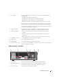
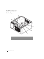
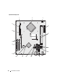
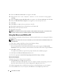
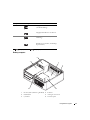
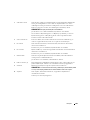
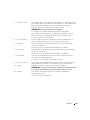
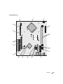
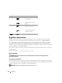
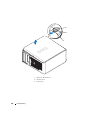
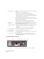
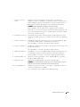
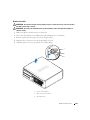
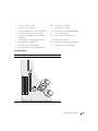
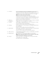
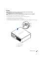
Desktop Computer — Back View
5 power light The power light illuminates and blinks or remains solid to indicate different
operating states:
• No light — The computer is turned off.
• Steady green — The computer is in a normal operating state.
• Blinking green — The computer is in a power-saving mode.
• Blinking or solid amber — See "Power Problems" in your online
User’s Guide
.
To exit from a power-saving mode, press the power button or use the keyboard or
the mouse if it is configured as a wake device in the Windows Device Manager.
For a description of light codes that can help you troubleshoot problems with your
computer see "System Lights" on page 33.
6 diagnostic lights Use the lights to help you troubleshoot a computer problem based on the
diagnostic code. For more information, see "Diagnostic Lights" on page 34.
7 link integrity light
• Green — A good connection exists between a 10-Mbps network and the
computer.
• Orange — A good connection exists between a 100-Mbps network and the
computer.
• Off — The computer is not detecting a physical connection to the network.
8 headphone connector Use the headphone connector to attach headphones.
9 floppy drive Insert a floppy disk into this drive.
10 CD/DVD drive Insert a CD or DVD (if supported) into this drive.
11 location of Service Tag Use the Service Tag to identify your computer when you access the Dell Support
website or call technical support.
1 card slots Access connectors for any installed PCI and PCI Express Cards.
2 back-panel connectors Plug serial, USB, and other devices into the appropriate connector.
See "Desktop Computer — Back-Panel Connectors" on page 18.
3 power connector Insert the power cable into this connector.
5
1
2 3 4 6

18 Quick Reference Guide
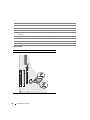
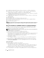
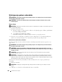
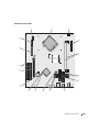
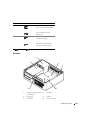
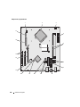
Desktop Computer — Back-Panel Connectors
4 voltage selection switch Your computer is equipped with a manual voltage-selection switch. To avoid
damaging a computer with a manual voltage-selection switch, set the switch for
the voltage that most closely matches the AC power available in your location.
NOTICE: In Japan, the voltage-selection switch must be set to the 115-V
position.
Also, ensure that your monitor and attached devices are electrically rated to
operate with the AC power available in your location.
5 padlock ring Insert a padlock to lock the computer cover.
6 cover release latch Use this latch to open the computer cover.
1
parallel connector
Connect a parallel device, such as a printer, to the parallel connector. If you have a
USB printer, plug it into a USB connector.
NOTE: The integrated parallel connector is automatically disabled if the computer
detects an installed card containing a parallel connector configured to the same
address. For more information, see your online User’s Guide.
2
link integrity light • Green — A good connection exists between a 10-Mbps network and the
computer.
• Orange — A good connection exists between a 100-Mbps network and the
computer.
• Off — The computer is not detecting a physical connection to the network.
13
10 9 8
5
6
7
24

Quick Reference Guide 19
3
network adapter
connector
To attach your computer to a network or broadband device, connect one end of a
network cable to either a network jack or your network or broadband device.
Connect the other end of the network cable to the network adapter connector on
the back panel of your computer. A click indicates that the network cable has been
securely attached.
NOTE: Do not plug a telephone cable into the network connector.
On computers with a network adapter card, use the connector on the card.
It is recommended that you use Category 5 wiring and connectors for your
network. If you must use Category 3 wiring, force the network speed to 10 Mbps
to ensure reliable operation.
4
network activity light
This light flashes yellow when the computer is transmitting or receiving network
data. A high volume of network traffic may make this light appear to be in a steady
"on" state.
5
line-in connector
Use the blue line-in connector to attach a record/playback device such as a
cassette player, CD player, or VCR.
On computers with a sound card, use the connector on the card.
6
line-out connector
Use the green line-out connector to attach headphones and most speakers with
integrated amplifiers.
On computers with a sound card, use the connector on the card.
7
microphone connector
Use the pink microphone connector to attach a personal computer microphone
for voice or musical input into a sound or telephony program.
On computers with a sound card, the microphone connector is on the card.
8
USB 2.0 connectors (4)
Use the back USB connectors for devices that typically remain connected, such as
printers and keyboards.
9
video connector
Plug the cable from your VGA-compatible monitor into the blue connector.
NOTE: If you purchased an optional graphics card, this connector will be covered by
a cap. Connect your monitor to the connector on the graphics card. Do not remove
the cap.
10
serial connector
Connect a serial device, such as a handheld device, to the serial port. The default
designation is COM1 for serial connector 1.
For more information, see your online User’s Guide.

20 Quick Reference Guide
Removing the Computer Cover
CAUTION: Before you begin any of the procedures in this section, follow the safety instructions in the Product
Information Guide.
CAUTION: To guard against electrical shock, always unplug your computer from the electrical outlet before
removing the cover.
Before You Begin
NOTICE: To avoid losing data, save and close any open files and exit any open programs before you turn off your
computer.
1
Shut down the operating system:
a
Save and close any open files, exit any open programs, click the
Start
button, and then click
Tu rn
Off Computer
.
b
In the
Turn off computer
window, click
Tur n off
.
The computer turns off after the operating system shutdown process finishes.
2
Ensure that the computer and any attached devices are turned off. If your computer and attached
devices did not automatically turn off when you shut down your operating system, turn them off now.
Before Working Inside Your Computer
Use the following safety guidelines to help protect your computer from potential damage and to help
ensure your own personal safety.
CAUTION: Before you begin any of the procedures in this section, follow the safety instructions in the Product
Information Guide.
CAUTION: Handle components and cards with care. Do not touch the components or contacts on a card. Hold a
card by its edges or by its metal mounting bracket. Hold a component such as a processor by its edges, not by
its pins.
NOTICE: Only a certified service technician should perform repairs on your computer. Damage due to servicing
that is not authorized by Dell is not covered by your warranty.
NOTICE: When you disconnect a cable, pull on its connector or on its strain-relief loop, not on the cable itself.
Some cables have a connector with locking tabs; if you are disconnecting this type of cable, press in on the locking
tabs before you disconnect the cable. As you pull connectors apart, keep them evenly aligned to avoid bending any
connector pins. Also, before you connect a cable, ensure that both connectors are correctly oriented and aligned.
To avoid damaging the computer, perform the following steps before you begin working inside the
computer.
1
Turn off your computer.
NOTICE: To disconnect a network cable, first unplug the cable from your computer and then unplug it from the
network wall jack.
Sidan laddas ...
Sidan laddas ...
Sidan laddas ...
Sidan laddas ...
Sidan laddas ...
Sidan laddas ...
Sidan laddas ...
Sidan laddas ...
Sidan laddas ...
Sidan laddas ...
Sidan laddas ...
Sidan laddas ...
Sidan laddas ...
Sidan laddas ...
Sidan laddas ...
Sidan laddas ...
Sidan laddas ...
Sidan laddas ...
Sidan laddas ...
Sidan laddas ...
Sidan laddas ...
Sidan laddas ...
Sidan laddas ...
Sidan laddas ...
Sidan laddas ...
Sidan laddas ...
Sidan laddas ...
Sidan laddas ...
Sidan laddas ...
Sidan laddas ...
Sidan laddas ...
Sidan laddas ...
Sidan laddas ...
Sidan laddas ...
Sidan laddas ...
Sidan laddas ...
Sidan laddas ...
Sidan laddas ...
Sidan laddas ...
Sidan laddas ...
Sidan laddas ...
Sidan laddas ...
Sidan laddas ...
Sidan laddas ...
Sidan laddas ...
Sidan laddas ...
Sidan laddas ...
Sidan laddas ...
Sidan laddas ...
Sidan laddas ...
Sidan laddas ...
Sidan laddas ...
Sidan laddas ...
Sidan laddas ...
Sidan laddas ...
Sidan laddas ...
Sidan laddas ...
Sidan laddas ...
Sidan laddas ...
Sidan laddas ...
Sidan laddas ...
Sidan laddas ...
Sidan laddas ...
Sidan laddas ...
Sidan laddas ...
Sidan laddas ...
Sidan laddas ...
Sidan laddas ...
Sidan laddas ...
Sidan laddas ...
Sidan laddas ...
Sidan laddas ...
Sidan laddas ...
Sidan laddas ...
Sidan laddas ...
Sidan laddas ...
Sidan laddas ...
Sidan laddas ...
Sidan laddas ...
Sidan laddas ...
Sidan laddas ...
Sidan laddas ...
Sidan laddas ...
Sidan laddas ...
Sidan laddas ...
Sidan laddas ...
Sidan laddas ...
Sidan laddas ...
Sidan laddas ...
Sidan laddas ...
Sidan laddas ...
Sidan laddas ...
Sidan laddas ...
Sidan laddas ...
Sidan laddas ...
Sidan laddas ...
Sidan laddas ...
Sidan laddas ...
Sidan laddas ...
Sidan laddas ...
Sidan laddas ...
Sidan laddas ...
Sidan laddas ...
Sidan laddas ...
Sidan laddas ...
Sidan laddas ...
Sidan laddas ...
Sidan laddas ...
Sidan laddas ...
Sidan laddas ...
Sidan laddas ...
Sidan laddas ...
Sidan laddas ...
Sidan laddas ...
Sidan laddas ...
Sidan laddas ...
Sidan laddas ...
Sidan laddas ...
Sidan laddas ...
Sidan laddas ...
Sidan laddas ...
Sidan laddas ...
Sidan laddas ...
Sidan laddas ...
Sidan laddas ...
Sidan laddas ...
Sidan laddas ...
Sidan laddas ...
Sidan laddas ...
Sidan laddas ...
Sidan laddas ...
Sidan laddas ...
Sidan laddas ...
Sidan laddas ...
Sidan laddas ...
Sidan laddas ...
Sidan laddas ...
Sidan laddas ...
Sidan laddas ...
Sidan laddas ...
Sidan laddas ...
Sidan laddas ...
Sidan laddas ...
Sidan laddas ...
Sidan laddas ...
Sidan laddas ...
Sidan laddas ...
Sidan laddas ...
Sidan laddas ...
Sidan laddas ...
Sidan laddas ...
Sidan laddas ...
Sidan laddas ...
Sidan laddas ...
Sidan laddas ...
Sidan laddas ...
Sidan laddas ...
Sidan laddas ...
Sidan laddas ...
Sidan laddas ...
Sidan laddas ...
Sidan laddas ...
Sidan laddas ...
Sidan laddas ...
Sidan laddas ...
Sidan laddas ...
Sidan laddas ...
Sidan laddas ...
Sidan laddas ...
Sidan laddas ...
Sidan laddas ...
Sidan laddas ...
Sidan laddas ...
Sidan laddas ...
Sidan laddas ...
Sidan laddas ...
Sidan laddas ...
Sidan laddas ...
Sidan laddas ...
Sidan laddas ...
Sidan laddas ...
Sidan laddas ...
Sidan laddas ...
Sidan laddas ...
Sidan laddas ...
Sidan laddas ...
Sidan laddas ...
Sidan laddas ...
Sidan laddas ...
Sidan laddas ...
Sidan laddas ...
Sidan laddas ...
Sidan laddas ...
Sidan laddas ...
Sidan laddas ...
Sidan laddas ...
Sidan laddas ...
Sidan laddas ...
Sidan laddas ...
Sidan laddas ...
Sidan laddas ...
Sidan laddas ...
Sidan laddas ...
Sidan laddas ...
Sidan laddas ...
Sidan laddas ...
Sidan laddas ...
Sidan laddas ...
Sidan laddas ...
Sidan laddas ...
Sidan laddas ...
Sidan laddas ...
Sidan laddas ...
Sidan laddas ...
Sidan laddas ...
Sidan laddas ...
Sidan laddas ...
Sidan laddas ...
Sidan laddas ...
Sidan laddas ...
Sidan laddas ...
Sidan laddas ...
Sidan laddas ...
Sidan laddas ...
Sidan laddas ...
Sidan laddas ...
Sidan laddas ...
Sidan laddas ...
Sidan laddas ...
Sidan laddas ...
Sidan laddas ...
Sidan laddas ...
Sidan laddas ...
Sidan laddas ...
Sidan laddas ...
Sidan laddas ...
Sidan laddas ...
Sidan laddas ...
Sidan laddas ...
Sidan laddas ...
Sidan laddas ...
Sidan laddas ...
Sidan laddas ...
Sidan laddas ...
Sidan laddas ...
Sidan laddas ...
Sidan laddas ...
Sidan laddas ...
Sidan laddas ...
Sidan laddas ...
Sidan laddas ...
Sidan laddas ...
Sidan laddas ...
Sidan laddas ...
Sidan laddas ...
Sidan laddas ...
Sidan laddas ...
Sidan laddas ...
Sidan laddas ...
Sidan laddas ...
Sidan laddas ...
Sidan laddas ...
Sidan laddas ...
Sidan laddas ...
Sidan laddas ...
Sidan laddas ...
Sidan laddas ...
Sidan laddas ...
Sidan laddas ...
Sidan laddas ...
Sidan laddas ...
Sidan laddas ...
Sidan laddas ...
Sidan laddas ...
Sidan laddas ...
Sidan laddas ...
Sidan laddas ...
Sidan laddas ...
Sidan laddas ...
Sidan laddas ...
Sidan laddas ...
Sidan laddas ...
Sidan laddas ...
Sidan laddas ...
Sidan laddas ...
Sidan laddas ...
Sidan laddas ...
Sidan laddas ...
Sidan laddas ...
Sidan laddas ...
Sidan laddas ...
Sidan laddas ...
Sidan laddas ...
Sidan laddas ...
Sidan laddas ...
Sidan laddas ...
Sidan laddas ...
Sidan laddas ...
Sidan laddas ...
Sidan laddas ...
Sidan laddas ...
Sidan laddas ...
Sidan laddas ...
Sidan laddas ...
Sidan laddas ...
Sidan laddas ...
Sidan laddas ...
Sidan laddas ...
Sidan laddas ...
Sidan laddas ...
Sidan laddas ...
Sidan laddas ...
Sidan laddas ...
Sidan laddas ...
Sidan laddas ...
Sidan laddas ...
Sidan laddas ...
Sidan laddas ...
Sidan laddas ...
Sidan laddas ...
Sidan laddas ...
Sidan laddas ...
Sidan laddas ...
Sidan laddas ...
Sidan laddas ...
Sidan laddas ...
Sidan laddas ...
Sidan laddas ...
Sidan laddas ...
Sidan laddas ...
Sidan laddas ...
Sidan laddas ...
Sidan laddas ...
Sidan laddas ...
Sidan laddas ...
Sidan laddas ...
-
 1
1
-
 2
2
-
 3
3
-
 4
4
-
 5
5
-
 6
6
-
 7
7
-
 8
8
-
 9
9
-
 10
10
-
 11
11
-
 12
12
-
 13
13
-
 14
14
-
 15
15
-
 16
16
-
 17
17
-
 18
18
-
 19
19
-
 20
20
-
 21
21
-
 22
22
-
 23
23
-
 24
24
-
 25
25
-
 26
26
-
 27
27
-
 28
28
-
 29
29
-
 30
30
-
 31
31
-
 32
32
-
 33
33
-
 34
34
-
 35
35
-
 36
36
-
 37
37
-
 38
38
-
 39
39
-
 40
40
-
 41
41
-
 42
42
-
 43
43
-
 44
44
-
 45
45
-
 46
46
-
 47
47
-
 48
48
-
 49
49
-
 50
50
-
 51
51
-
 52
52
-
 53
53
-
 54
54
-
 55
55
-
 56
56
-
 57
57
-
 58
58
-
 59
59
-
 60
60
-
 61
61
-
 62
62
-
 63
63
-
 64
64
-
 65
65
-
 66
66
-
 67
67
-
 68
68
-
 69
69
-
 70
70
-
 71
71
-
 72
72
-
 73
73
-
 74
74
-
 75
75
-
 76
76
-
 77
77
-
 78
78
-
 79
79
-
 80
80
-
 81
81
-
 82
82
-
 83
83
-
 84
84
-
 85
85
-
 86
86
-
 87
87
-
 88
88
-
 89
89
-
 90
90
-
 91
91
-
 92
92
-
 93
93
-
 94
94
-
 95
95
-
 96
96
-
 97
97
-
 98
98
-
 99
99
-
 100
100
-
 101
101
-
 102
102
-
 103
103
-
 104
104
-
 105
105
-
 106
106
-
 107
107
-
 108
108
-
 109
109
-
 110
110
-
 111
111
-
 112
112
-
 113
113
-
 114
114
-
 115
115
-
 116
116
-
 117
117
-
 118
118
-
 119
119
-
 120
120
-
 121
121
-
 122
122
-
 123
123
-
 124
124
-
 125
125
-
 126
126
-
 127
127
-
 128
128
-
 129
129
-
 130
130
-
 131
131
-
 132
132
-
 133
133
-
 134
134
-
 135
135
-
 136
136
-
 137
137
-
 138
138
-
 139
139
-
 140
140
-
 141
141
-
 142
142
-
 143
143
-
 144
144
-
 145
145
-
 146
146
-
 147
147
-
 148
148
-
 149
149
-
 150
150
-
 151
151
-
 152
152
-
 153
153
-
 154
154
-
 155
155
-
 156
156
-
 157
157
-
 158
158
-
 159
159
-
 160
160
-
 161
161
-
 162
162
-
 163
163
-
 164
164
-
 165
165
-
 166
166
-
 167
167
-
 168
168
-
 169
169
-
 170
170
-
 171
171
-
 172
172
-
 173
173
-
 174
174
-
 175
175
-
 176
176
-
 177
177
-
 178
178
-
 179
179
-
 180
180
-
 181
181
-
 182
182
-
 183
183
-
 184
184
-
 185
185
-
 186
186
-
 187
187
-
 188
188
-
 189
189
-
 190
190
-
 191
191
-
 192
192
-
 193
193
-
 194
194
-
 195
195
-
 196
196
-
 197
197
-
 198
198
-
 199
199
-
 200
200
-
 201
201
-
 202
202
-
 203
203
-
 204
204
-
 205
205
-
 206
206
-
 207
207
-
 208
208
-
 209
209
-
 210
210
-
 211
211
-
 212
212
-
 213
213
-
 214
214
-
 215
215
-
 216
216
-
 217
217
-
 218
218
-
 219
219
-
 220
220
-
 221
221
-
 222
222
-
 223
223
-
 224
224
-
 225
225
-
 226
226
-
 227
227
-
 228
228
-
 229
229
-
 230
230
-
 231
231
-
 232
232
-
 233
233
-
 234
234
-
 235
235
-
 236
236
-
 237
237
-
 238
238
-
 239
239
-
 240
240
-
 241
241
-
 242
242
-
 243
243
-
 244
244
-
 245
245
-
 246
246
-
 247
247
-
 248
248
-
 249
249
-
 250
250
-
 251
251
-
 252
252
-
 253
253
-
 254
254
-
 255
255
-
 256
256
-
 257
257
-
 258
258
-
 259
259
-
 260
260
-
 261
261
-
 262
262
-
 263
263
-
 264
264
-
 265
265
-
 266
266
-
 267
267
-
 268
268
-
 269
269
-
 270
270
-
 271
271
-
 272
272
-
 273
273
-
 274
274
-
 275
275
-
 276
276
-
 277
277
-
 278
278
-
 279
279
-
 280
280
-
 281
281
-
 282
282
-
 283
283
-
 284
284
-
 285
285
-
 286
286
-
 287
287
-
 288
288
-
 289
289
-
 290
290
-
 291
291
-
 292
292
-
 293
293
-
 294
294
-
 295
295
-
 296
296
-
 297
297
-
 298
298
-
 299
299
-
 300
300
-
 301
301
-
 302
302
-
 303
303
-
 304
304
-
 305
305
-
 306
306
-
 307
307
-
 308
308
-
 309
309
-
 310
310
-
 311
311
-
 312
312
-
 313
313
-
 314
314
-
 315
315
-
 316
316
-
 317
317
-
 318
318
-
 319
319
-
 320
320
-
 321
321
-
 322
322
-
 323
323
-
 324
324
-
 325
325
-
 326
326
-
 327
327
-
 328
328
-
 329
329
-
 330
330
-
 331
331
-
 332
332
-
 333
333
-
 334
334
-
 335
335
-
 336
336
-
 337
337
-
 338
338
-
 339
339
-
 340
340
-
 341
341
-
 342
342
-
 343
343
-
 344
344
-
 345
345
-
 346
346
-
 347
347
-
 348
348
-
 349
349
-
 350
350
-
 351
351
-
 352
352
-
 353
353
-
 354
354
-
 355
355
-
 356
356


Dell OptiPlex 320 Snabbstartsguide
- Kategori
- Mixer / matberedare tillbehör
- Typ
- Snabbstartsguide
på andra språk
- slovenčina: Dell OptiPlex 320 Stručná príručka spustenia
- dansk: Dell OptiPlex 320 Hurtig start guide